GB Patent: GB-190,902,121
|
| Improvements in Multiple Straight-Blade Sawing Machines
|
|
Patentee:
|
|
| Charles Wicksteed (exact or similar names) - Kettering, Northampton County, England |
|
|
Patent Dates:
|
| Applied: |
Jan. 28, 1909 |
| Granted: |
Jul. 01, 1909 |
|
Patent Pictures:
[
1 | 2 | 3
]
|
|
|
Espacenet patent
Report data errors or omissions to steward
Joel Havens
|
|
Description: |
| Abstract:
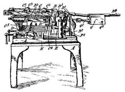
In a multiple machine hack-saw for metals, the saw-carrying frames reciprocate upon a gantry B pivoted at B<1> to standards B<2>. The saws H are mounted side by side in the free ends of saw-holders carried by transverse rods D and radiated fanwise, as shown in Fig. 2, to allow room for the blade-tensioning devices, which consist of tubular sockets I, each slotted to accommodate the screw-adjusted movable arm C<5> of the saw - holder. Each saw - holder has two perforated bosses C' screwed on to the rod D, so that the distances between the saws H can be adjusted. Each saw is gripped between the saw - holder C<5> and a plate - spring C<7>. The central saw-holder C carries two slides C<2> which grip the side bars of the gantry B. The saws are reciprocated from the crank-disk F' by means of a connecting-rod E pivoted to an arm C', and a second crank on the shaft F of the disk F' reciprocates a balance weight G sliding on the tail-rod of the gantry, so that the weight G and the saw-frames are at their greatest distance from the pivot B' at the same time. The gantry B is cushioned by an adjustable spring buffer K<3> when the work is nearly cut through. The buffer comprises a tubular socket closed by a screw plug. Against the inner end of the plug rests a nut, which receives the adjustment screw K<3> and is kept against the plug by a strong coiled spring. The mechanism shown in Fig. 3 lifts the saws from the bottom of the cut on the return stroke, and allows the full weight of the saw frame to be on the saws during the cutting-stroke. A double-barrelled pump M is pivoted at L<1> in an oil-tank. The barrel M' carries a plunger M<2> having a rod pivoted at B' to the gantry B. The barrel M<4> has a port M<6> opening into the oil-tank and closed by the plunger M<5> when at or near its innermost position. The plunger M<5> is reciprocated by an eccentric N on the main shaft F. During the cutting-stroke, the plunger M<5> is retracted so as to open the port M<6> and allow the plunger M<2> to descend under the weight of the saw frame. As the saws reach the end of their stroke, the return of the plunger M<5> closes the port M<6> and forces upwards the plunger M<2> and the gantry and saws. The port M<6> is uncovered again at the commencement of the working stroke of the saws, and the plunger M<2> forces out a little oil, thus allowing the weight of the frame to press the saws further down for a fresh cut. A passage M<7>, closed by a ball valve, is provided to re-admit oil to the pump when the work is completed and the gantry is raised to take the saws out of the work. |
|

)
)
)