|
Description: |
| Most of the patents prior to 1836 were lost in the Dec. 1836 fire. Only about 2,000 of the almost 10,000 documents were recovered. Little is known about this patent. There are no patent drawings available. This patent is in the database for reference only.
“Specification of a patent for some improvements in the boilers of Steam Engines. Granted to Anthony Hermange, Baltimore, Maryland, November 26th, 1828.
To give a sufficient description of my improvements in steam boilers, it will not be necessary to enter into an account of steam boilers now in use; as they are, of course, very various, and well enough known, to distinguish them from my modes of construction. The boiler itself, with regard to its outward contour, I will make of any convenient shape. As convenient a one as any, will be to have it of a cylindrical form, or of that of a parallelopiped; or this last surmounted by a half cylinder; or of a prism, whose base is a hexagon; of a cubical, or indeed of a variety of forms. I will place the fire-place, and flue, and fuel-pipe, (where I have one especially for that purpose, particularly when the fuel to be used is coal) inside of the boiler, disposing of them in such a manner, that when the proper quantity of water shall be in the boiler, they shall be below its surface. This will secure the advantage of having the water almost entirely to surround the fire-place, flue and fuel-pipe, where this last is employed. The flue, particularly, shall be lengthened out inside of the boiler, in a variety of ways, in order that it should present an extensive surface in contact with the water, and that the heat evolved in the fire-place, should thus, by means of the heated air freely circulating through the lengthened flue, be all, or nearly all, communicated to the water before the flue passes out of the boiler. The flue will, in this manner, have an effect somewhat analogous to that of a reverberatory furnace. I said the flue may be lengthened out in a variety of ways; it may, for example, go from the fire-place perpendicularly upwards for some way, then form an arch, and return vertically downwards, and have its exit from a convenient place in the lower part of the boiler, or thereabouts; this would be one of the simplest methods. After ascending as before, the flue may have a tortuous, or spiral, disposition downwards, and have also its exit as before.The main flue may also, above, be divided into two, three, four, or more, smaller flues, as convenience may dictate, and these again may be connected together in the bottom part of the boiler, or towards the bottom, for their exit from the boiler, by a single flue or more; from the fire-place, the flue may have a serpentine form in the boiler, and have its exit at any convenient place. In fact, it will readily be perceived that a variety of modes may be adopted. The fire-place I will construct of any convenient form, and place it in any position that the easy introduction of fuel, or any other such circumstance, shall require. It may, for instance, be placed at the bottom of the boiler, with a grate opening into a wind-box below the boiler; in this way, the fuel-pipe may communicate from the side of the boiler, at an angle from the horizon, sufficiently inclined to permit the fuel to fall with facility into the fire-place. This would be an excellent disposition, when the fuel to be used is coal; a coal-receiver, with two sliders, or doors, may thus be adapted to the outside end of the fuel pipe, in order that, at the instant of supplying fuel to the fire, the heated air in the fuel-pipe may not be suffered to escape. When the fuel is to consist of wood, it would, no doubt, be better to have the fire-place opening, for the reception of the wood, on the side of the boiler, or the end of it, by means of a door a little above the bottom of it; so that the water may also come in contact with the bottom of the fire-place. In this way, also, there may be practiced, if convenience requires it, an opening through the bottom of the fire-place, (across which, a grate may be placed, through which the ashes may drop) communicating with an opening through the bottom of the boiler, which may there have a wind, or blast, box, attached to it. It will be perceived that the arrangement may be various. As in the combustion of the fuel, with regard to boilers in common use, much of its inflammable substance passes off in the form of dense smoke, &c. without entering into a perfect state of combustion, I will employ bellows (conveniently adapted for the purpose, and which may, of course, be worked by the engine itself) for the purpose of keeping up a constant current of atmospheric air through the ignited fuel, and to keep up the current of air, thus heated, throughout the course of the flue. As the air, in approaching towards the exit of the flue, from the boiler, will become cooler, and, of course, from its increased density be of less volume, it will be well, ordinarily, to diminish the flue, gradually, as it approaches its exit. I will avoid bringing the fuel pipe (where one is used,) or the flue, into that part of the boiler occupied by steam, for the following reason: the fuel-pipe and flue, having a direct communication with the fire-place, would, of course, always be filled with air intensely heated, which would be extremely likely to keep them in a red hot state; in this condition, being in contact with steam, a constant decomposition of portions of the steam would take place; its oxygen combining with the metal, would rapidly corrode it, to the evident danger, after a little use, of the bursting of the boiler; whilst hydrogen gas would be extricated, during the progress of decomposition, which might interrupt the free and secure motion of the rest of the machinery of the engine. the purpose of ascertaining, always, the height of the water in the boiler, I will make use of any description of water-gauge that may be adapted to ordinary steam-boilers: a very good one will be to have two short pipes accurately inserted into the boiler; one, into that part occupied by the water, and the other into that containing the steam; and the communication with both formed on the outside of the boiler, by means of a strong glass tube; in this way, the height of water may always be determined by sight. A stop-cock may be used; but will not, of course, be so convenient as the water-gauge above. It would be well to have the steam-pipe going off from, or near, the most elevated part of the boiler; this will be a matter of convenience. For supplying the boiler with water, I will make use of any of the ordinary means. The pump for the supply of water may be so managed as to have at will, a longer or shorter stroke, according to the demand of the boiler for water. In the construction of these improvements, I will employ any description of metal in common use for steam-boilers; but I need not add, that copper would be the best. The blast-box, where one is used, will, of course, vary in its structure, according to the most suitable adaptation to the boiler, as well as the bellows employed. The wind-pipe of the bellows may either be adapted to a blast-box, or may be moveable, so as to pass through a hole made in the door of the fire-place, (where there is a door) or permanently fixed under the door, or at its side, or indeed in any other convenient situation. As for the fastenings, or other modes of adapting the several parts of the boiler, &c. together, I need hardly mention that I will adopt any convenient modes now in common practice in similar cases.
After the exit of the flue from the boiler, it may, if thought proper, be carried through the water tank, or vessel, destined to keep up the supply for the boiler, for the purpose of heating it before it is pumped into the boiler. No doubt, most of the principles laid down in the preceding descriptions, have, taken separately, been heretofore known; but I claim as my own, the combinations of principles therein stated.
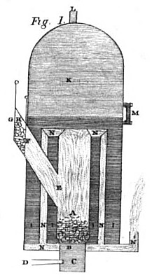
Description of the Drawings-Plate 4.
Fig. 1, is a vertical section, showing the internal structure of the boiler, &c. The fuel fitted for a boiler made in this way would be coal.
a, the fire-place.
b, the grate.
c, the blast-box, with a slide, or door, at the bottom.
d, the wind-pipe of the bellows.
e, the fuel-pipe.
f, a sliding door, shutting the fuel-pipe, and when opened, permitting fuel to drop down from the fuel-receiver.
g, another sliding door, stopping the communication from the open air, when the slide f, is open.
h, the fuel-receiver, or box.
i, i, i, space of the boiler occupied by the water.
k, space of the boiler filled with steam.
1, steam-pipe.
m, water-gauge.
n, n, n, flue-pipes: there may be four, more or less, passing down through the bottom of the boiler, and ending in a single larger fluepipe.
Fig. 2, represents the bottom of the boiler, pierced by the flue-pipes n, n, &c.-b is the grate at the bottom of the fire-place.
n', is a larger flue, forming the exit from a flue, or heat-box, below the boiler; n, n, open into this flue-box, after having pierced through the bottom of the boiler.
Fig. 3, represents n, n, passing into flue-pipes, instead of passing from the boiler into a flue-box below. These flue-pipes p, p, communicate with n'; they might, if convenient, be placed under the boiler.
Fig. 4, is a middle section of a boiler in the form of a parallelopiped, surmounted by a half cylinder. This is an excellent mode when the fuel is wood. When similar letters to those in Fig. 1, are used, they represent portions of the boiler, &c., intended for similar purposes. The dotted additions to the figure (b, c, d,) show how a grate, wind-box, and the wind-pipe of the bellows may be adopted. o, is the door of the fire-place.”
Journal of the Franklin Institute Vol. 8, Nov. 1829 pgs. 339-341
|
|

)
)
)
)