|
Description: |
| Most of the patents prior to 1836 were lost in the Dec. 1836 fire. Only about 2,000 of the almost 10,000 documents were recovered. Little is known about this patent. Only the patent drawing is available. This patent is in the database for reference only.
“Specification of a patent for an Improvement in the Rail-Road and a Car adapted to run thereon, by means of which, roads, either curved or straight, are passed with equal facility. Granted to James Wright, Columbia, Lancaster County, Pennsylvania, April 17, 1829.
The improvement in the car consists in the construction of the wheels, which are so formed, that each wheel has two, three, or more rims of different diameters, with shoulders which serve as flanches, to keep the wheel upon the rail. The number of rims will depend upon the number of different curves in the different parts of the road.
Where the curves are all of the same radius, two rims only will be required to each wheel. When the car, or carriage, runs upon a straight road, rims of equal diameters run upon the rails; when upon a curved road, the diameters of the rims employed, are, to each other, as the radii of the inner and the outer rails.
When the carriage leaves a curved for a straight road, a straight for a curved road, or one curve for another, the rails, at their places of meeting, do not form a continued line, nor are they on the same plane, a lateral offset being made, so that the rims of the proper diameters may take upon the new section, either straight or curved, upon which they are to pass. The difference in the elevation of the rails, is also made to correspond with the difference in the diameters of the rims, so that the wheels pass from one rail to another, without any jolt, or variation in the horizontal position of their axes.
What I claim as new is the whole of the arrangement herein described, by which the rims of different diameters upon the same wheel are adapted to pass upon rails, either straight or of different curvatures, and the laying of the rails in the manner described, so as to correspond with the structure of the wheels, without regard to the manner in which the carriage, or the road, is formed in other respects.
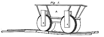
References to the drawing, Plate 3. Fig. 1.
A, the car, each wheel of which has flanches, and rims which are of different diameters.
B, B, the higher rails, which receive the rims of the smaller diameter; these rails are always on the inner line of the circle to be traversed.
C, C, the lower rails, which always bear the wheels in their full size.”
Journal of the Franklin Institute Vol. 7, Oct. 1829 pg. 270
|
|

)
)