|
Description: |
| Abstract:
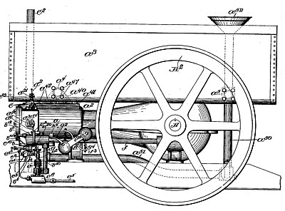
The present invention relates to an explosion-engine, and the engine embodying the invention is mainly intended to be used with gasolene or other liquid explosives, although certain features of the invention may be equally well utilized in engines in which gas is to be used as the explosive element.
The invention relates to governing mechanism of novel construction and arrangement whereby the exhaust-valve, which is opened at the end of each effective stroke, is maintained open when the engine is up to speed, the same operation of the governor preventing the opening of the gas-inlet valve and the operation of the pump, so that no energy is wasted, while, moreover, since the exhaust valve remains open air is directly admitted to the cylinder, tending to cool the same during the time that there are no explosions. To these ends the exhaust-valve is so arranged as to be positively opened at the necessary intervals and to be closed by a yielding force, as that of a spring, while the governor, which is of the centrifugal type, is arranged to cooperate With a pawl adapted to engage and hold open the exhaust-valve when the speed has risen sufficiently to need checking. The said pawl normally stands in the path of an operating-lever which is arranged to open the exhaust; but as the said lever tends to move 0 back after the exhaust is open the said pawl is momentarily moved or tripped by the governing device, so as not to catch the said arm and hold the exhaust valve open. The centrifugal action of the governor is, however, such as to cause it to fail to operate upon said pawl at a certain speed, and the pawl, therefore, under such conditions catches the exhaust-operating lever and remains in engagement therewith until the speed has come down sufficiently to permit the pawl to be tripped by the governor.
The gas-inlet valve and pump instead of being acted upon directly by the governor itself may be controlled through the operation of the exhaust-valve or its lever, the inlet valve being herein shown as controlled by a lever, which is arranged to be actuated by a suitable cam. The said lever is provided with a cam-roll which is movable with relation thereto into and out of the path of the cam by which the said lever is operated, and the movement of said roll is controlled by the operation of the exhaust valve lever. This may be accomplished by providing the shaft which carries the cam for the inlet valve lever with a secondary cam or engaging surface in advance of the operating-cam, the said secondary cam at each rotation moving the cam-roll out of the path of the main cam. The said cam-roll, however, is arranged to be operated upon also by the exhaust-valve lever to restore it to its normal position, this operation taking place in the closing movement of the exhaust valve, and consequently not taking place at all when the exhaust valve remains open, as above described.
The pump-plunger is arranged to be positively moved in both directions, the down stroke being produced by a cam, which operates directly on the pump-plunger, and the upstroke being produced by the movement of the gas-inlet-valve lever, which opens the said valve, such movement not occurring when the engine is up to speed.
The igniting device comprises an electrical circuit-breaker having a rotary contact within the explosive-chamber, the said contact piece being provided with a ratchet-wheel at the outside of the chamber, which is operated by a pawl connected with a reciprocating member, which cooperates with the lever which controls the gas-inlet valve. The said circuit-breaker is provided with novel means whereby it can be adjusted to compensate for wear or to determine the time of ignition, the fixed terminal of the circuit-breaker consisting of a wire held in a suitable clamp and longitudinally adjustable toward and from the rotary member. The said wire extends through a channel one surface of which is inclined, so that said wire is slightly bent from a straight line, and thereby placed under spring tension. The wire being of uniform diameter, it is obvious that when the same is turned with its socket, which is adjustable by being screw-threaded, the tension will be maintained throughout.
Claims:
1. The combination with the cylinder; of an inlet-valve and an exhaust-valve; levers for actuating said valves respectively; a cam for actuating the inlet-valve lever; a movable cam-roll connected with said lever; means for moving said cam-roll out of the path of the cam; and a projection from the exhaust-valve lever for moving said cam-roll into the path of the cam, substantially as described.
2. The combination with the cylinder; of an inlet-valve and an exhaust-valve; levers for actuating said valves respectively; a cam for actuating the inlet-valve lever; a movable cam-roll connected with said lever; means for moving said cam-roll out of the path of the cam; a projection from the exhaust valve lever for moving said cam-roll into the path of the cam; and a governor to control the operation of the exhaust-valve lever, substantially as described.
3. The combination with the cylinder of an explosion-engine; of an inlet-valve which controls the supply of the explosive to the cylinder; a pump for said explosive; an exhaust valve; an actuator for said exhaust valve; a governor to control said actuator; a common operating device for the said inlet valve and said pump; a movable cam-roll connected with said operating device; a cam cooperating with said cam-roll; and means connected with the exhaust-valve actuator for moving said cam-roll, substantially as described.
4. In an explosion-engine, the combination with a pump for supplying a liquid explosive, an inlet-valve to control the admission of said explosive to the cylinder, and an igniting device in said cylinder; of common means for operating said inlet-valve pump, and igniting device, an exhaust-valve; an actuator for said exhaust-valve, a governor to control the operation of said exhaust-valve, and means connected with the exhaust-valve actuator for controlling the said means for operating the inlet-valve pump and igniting device, substantially as described.
5. In an explosion-engine, the combination with an inlet-valve; of a lever adapted to operate said inlet-valve; a cam-roll secured to said lever but movable with relation thereto; a cam adapted to cooperate with said can1- roll; means operating at each revolution of said cam for moving said cam-roll out of the path of said cam to prevent the cooperation of said parts; a device normally operating at each revolution of said cam for restoring said cam-roll to its normal position before it is reached by the cam, and a governor for controlling said device, substantially as described.
6. In an explosion-engine, the combination with a cylinder; of inlet and exhaust valves arranged in opposite sides thereof and adapted to open inward; a single spring adapted to maintain both of the said valves closed; actuating-levers for said valves respectively, the said actuating-levers having a common axis; cams for operating said levers, and means connected with the exhaust-valve lever for controlling the operation of the inlet valve lever substantially as described.
7. The combination with the valves b2 and c2 of the levers b5 and c5 a bearing-support for said levers; a split hub formed on one of said levers bearing upon said bearing-support; and a forked bearing for the other 1ever also bearing upon said support, substantially as described.
8. The combination with the oppositely-disposed valves b2 and c2 of the spring c30 secured upon the stud c31 and adapted to maintain both of said valves seated; actuating-levers for opening said valves respectively, said levers being independent of each other but having a common axis; a shaft; and cams mounted on said shaft for operating said levers, substantially as described.
9. In an explosion-engine, the combination with the cylinder and piston; of a gas-inlet chamber communicating through a suitable inlet-valve with said inlet-chamber; a pump for supplying an explosive to said inlet-chamber; a cam for causing the effective stroke of said pump, in response to the revolution of the main shaft; a device for opening said inlet-valve, and means connected with said device for causing the return stroke of said pump, substantially as described.
10. In an explosion-engine, the combination with a cylinder and piston; of a gas-inlet chamber communicating through a suitable inlet-valve with said inlet-chamber; a pump for supplying an explosive to said inlet-chamber; a cam for causing the effective stroke of said pump, in response to the revolution of the main shaft; a device for opening said inlet-valve, said device also being provided with means for causing the return stroke of said pump; and a governor cooperating with the device for opening said inlet-valve, substantially as described.
11. In an explosion-engine, the combination with a self-closing exhaust-valve; of means for opening said valve; a pawl or detent adapted to prevent the closure of said valve; a governing device comprising a weight or weights mounted in a bearing transverse to a shaft adapted to be rotated in the operation of the engine; a tripping projection carried by said weight to cooperate with said pawl or detent to trip the same and permit the exhaust-valve to close, said tripping projection being adapted to move in response to centrifugal force to a position in which it will not trip the said pawl; an igniting device and inlet-valve and means cooperating with the exhaust-valve for operating said igniting device and inlet-valve, substantially as described.
12. The combination with a self-closing exhaust-valve, of an actuating-lever therefor, a cam cooperating with said lever to open the said valve, a governing device provided with means for engaging said lever and holding the valve open when the engine has reached a predetermined speed, an inlet-valve controlling the admission of the charge to the cylinder, an actuating-lever for said inlet-valve, a cam to cooperate with said lever, a movable member connected with said lever to be engaged directly by said cam, a device in advance of said cam for moving said member out of the path of said cam and an arm connected with the exhaust-valve lever to restore said member to its normal position in the return movement of said exhaust-valve lever, substantially as described.
13. In a gas-engine, the combination with the inlet-valve b2 of the actuating-lever b5 the cam b8 and laterally-movable cam-roll to cooperate therewith, the wing b10 in advance of said cam; the exhaust-valve; means for governing the operation of said exhaust-valve; and a device cooperating with the exhaust valve for restoring the said cam-roll in response to the closure of said exhaust-valve, substantially as described.
|
|