US Patent: 1,105,609
|
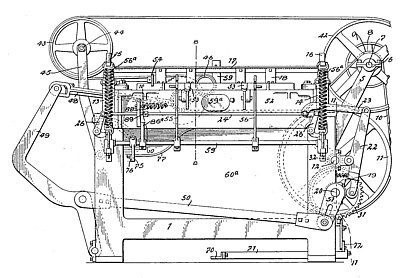
| Stave Jointing Machine
|
|
Patentee:
|
|
| Edwin F. Beugler (exact or similar names) - Buffalo, NY |
| Manufacturer: |
| Not known to have been produced |
|
|
Patent Dates:
|
| Applied: |
Mar. 13, 1913 |
| Granted: |
Aug. 04, 1914 |
USPTO (New site tip)
Google Patents
Report data errors or omissions to steward
Jeff Joslin
Vintage Machinery entry for E. & B. Holmes Machinery Co.
E. & B. Holmes Machinery Company / Buffalo Architectural History
E. & B. Holmes Machinery Co./ Forgotten Buffalo
E. & B. Holmes Machinery Company Building
|
|
Description: |
| A. J. Sangster - patent attorneyMy invention relates to stave jointing machines. The object of my invention is to provide a machine for jointing barrel staves possessing the improvements and advantages which will be evident from the following specification and the novel features particularly specified in the claims. It will be understood by those familiar with the art that barrel staves are formed from blanks or slats of wood, cut to the proper length and of varying widths. These blanks must be beveled on their edges to an angle approximately conformable to the barrel radius, and must also be so beveled on curved lines conformable to the desired bilge of the barrel; and, as will hereafter more fully appear, this curvature must be greater or less with reference to a given stave according to its width. By means of my improvements I am able to perform these several functions with speed and accuracy by using a circular saw and the several mechanisms and combinations which I will now describe by reference to the annexed drawings forming a part of this specification, and in which like characters of reference indicate corresponding parts.I claim:1. In a stave jointing machine, in combination with stave blank, holding means, a saw, a saw carriage, a bed upon which said carriage travels in horizontal plane, and means for causing said carriage to travel upon a curve on said plane and a curve varying in radius with the width of the stave blank comprising a carriage guide rigidly secured medially, blocks on said carriage engaging said guide, levers pivoted to the 85 free ends of said guide and fulcrumed to a fixed part of the machine,, and placing guides for moving a stave blank to position pivoted mediately to said levers.2. In a stave jointing machine, in combination with a saw constantly driven in rotation, means for imparting intermittent movement to other mechanisms cooperating therewith comprising a clutch member constantly driven, a clutch member intermittently driven, a lever for throwing said second-mentioned clutch member in and outof action, a brake for engaging said second clutch member and holding It out of action and against rotation until released by said lever. a bar acting upon said lever, a cam driven by a shaft driven by said clutch, a roller on said bar to contact with said cam for throwing said second member of said clutch out of action, a toggle for causing said bar to throw said clutch member into action, and a treadle governing said toggle.3. In a stave jointing machine, means for placing and holding a stave blank in position for jointing comprising a rest, placing arms for bearing against the front edge of the stave blank to adjust the same transversely, clamping means for holding said placing arms rigidly during the sawing operation, means for clamping the blank to said rest during the jointing, a saw carriage movable with relation to the rest, a guide for the saw carriage and means movable in proportion to the movement of the placing arms for adjusting the guide of the saw carriage.4. In a stave jointing machine, in combination with a saw and a saw carriage, a bed for said carriage for guiding the same in a horizontal plane, a guide for said carriage to direct its movement ever a curve to form the bilge curve of a stave, a shaft and a crank thereon for causing reciprocatory movement of said carriage, a lever and connecting rods for connecting said crank with said carriage, levers for bending said carriage guide on curves of varying radii, placing guides for placing a stave blank in position for jointing, and connections between said placing guides and said last-mentioned levers for causing bending of said carriage guide proportional to the width of the stave blank. |
|