GB Patent: GB-1,246,967
|
| Improvements in or relating to tool-holding mechanism for machine tools
|
|
Patentees:
|
| Herbert Rudolf Julius Zadow (exact or similar names) - Broadheath, Manchester, England |
| Curtis Albert Sparkes (exact or similar names) - Broadheath, Manchester, England |
|
|
Patent Dates:
|
| Applied: |
Nov. 14, 1967 |
| Granted: |
Sep. 22, 1971 |
Espacenet patent
Report data errors or omissions to steward
Jeff Joslin
"Vintage Machinery" entry for H. W. Kearns & Co., Ltd.
|
|
Description: |
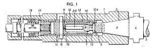
| "A machine tool spindle 1 contains an axially movable draw-bar 18 that operates spring-loaded jaws 10 for releasably engaging over an enlarged root 7 of a tool mandrel, and an extension of the draw-bar, e.g. a sleeve 12, is formed as a collet around the jaws and is axially slidable with the draw-bar between a position in which it allows the jaws to open and a position in which it holds the jaws closed with an axial component of compression of part of the jaws between the collet and the enlarged root of the tool mandrel. A conical end 3 of a tool or tool holder 5 is pulled into a tapered socket of the spindle 1 by means of the enlarged root 7 being gripped by the jaws 10. The sleeve 12 is attached to and movable with the draw-bar 18 and has a flange 12a that pulls the ends of the jaws 10 against the root 7 to hold the tool 5 into the tapered socket 2. A spring 19 biases the draw-bar to hold a tool in the socket and no tensile loads are applied to the connection of the jaw ends back to a block 11. In the embodiment shown the jaws 19 are resiliently integral with the block 11. In an alternative embodiment the arms are pivoted on the block 11 and constrained by an embracing coil garter spring. The sleeve 12 has openings 13 that allow the jaws 10 to be sprung open when the sleeve 12 is advanced against the spring 19 by, e.g., pneumatic pressure means. A pin-and-slot arrangement 14, 15, 16 limit the travel of the moving parts and an ejector 20 is provided. The block 11 may be spring biased away from the end 17 of the drawbar 18." |
|