|
Description: |
| Abstract:
This invention relates to grinders and particularly to a swinging frame grinder, and has for an object to provide a machine of this character which may be supported on a floor or suitable foundation, in which the grinding wheel will have universal adjustment and which grinder is so constructed that there are no supports or other elements extending above a certain height to interfere with the passage of a traveling crane over the machine.
It is also an object of the invention to provide a grinder in which the grinding wheel may be moved to practically any position desired and easily held therein by the operator.
Claims:
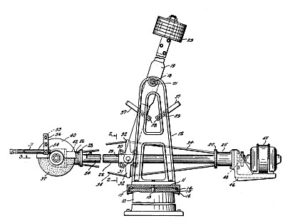
l. In a grinder, a base, an upright support mounted on said base and adapted to turnabout a vertical axis, an upright frame pivoted in said support, a housing pivoted in the frame, below the pivot for the frame, a grinding wheel carried by the housing and a motor for driving the wheel also carried by the housing.
2. In a grinder a base, an upright support mounted on said base and adapted to turn about a vertical axis, an upright frame pivoted in said support on a horizontal axis, a housing pivoted in the frame below the pivot for the frame and also; on a horizontal axis, a grinding wheel mounted in the housing and adapted for angular adjustment in the housing, and a motor carried by the housing for driving the wheel.
3. In a grinder, a base, an upright support mounted on said base and adapted to turn about a vertical axis, an upright frame pivoted in said support on a horizontal axis, a housing pivoted in said frame on a horizontal axis located below the said pivot for the frame, a grinding wheel, a support for the wheel carried by the housing adapted for angular adjustment thereon, means for clamping the support in different angular positions, a motor carried by the housing for driving said wheel, and one or more handles carried by the wheel support whereby it may be positioned and held during the grinding operation.
4. In a grinder, a base, an upright support mounted on said base and adapted to turn about a vertical axis, an upright frame mounted to swing on a horizontal axis in said support, a counter weight carried by said frame above said pivot, a housing pivoted in the frame below its pivot, a grinding wheel carried by the housing on one side of its pivot, a motor carried by the housing on the other side of its pivot, and a driving connection between the motor and wheel.
5. In a device of the character described, a base, an upright support mounted on said base and adapted to turn about a vertical axis, a frame mounted to swing in said support about a horizontal axis, a housing pivoted intermediate its length in said frame, a tool carried by the housing on one side of its pivot arranged for angular adjustment in said housing, means for clamping the tool in different adjusted positions, a motor carried by the housing on the other side of its pivot, and a driving connection between the motor and tool.
6. In a grinder, an upright support, a pivoted frame in said support adapted to swing about a horizontal axis, a housing comprising a tube, supporting, elements clamped to said tube intermediate its length on opposite sides thereof having trunnions pivoted in the frame and upright arms, tie rods extending over said arms and connected to the tube adjacent its opposite ends, a grinding wheel carried by the tube adjacent one end, a motor carried by the tube adjacent the other end, and a driving connection 'between the motor and wheel extending through said tube.
7. In a grinder, a support, a housing comprising a tube, supporting elements clamped to the opposite sides of the tube intermediate the ends thereof having trunnions pivoted in the support and upright arms, tie rods extending over said arms and secured to the tube adjacent the opposite ends thereof, a bracket carried by the tube at one end thereof, a motor mounted on said bracket, a casing mounted at the other end of said tube, a transverse shaft mounted in the casing, a grinding wheel mounted on said shaft, a shaft connected to the motor and extending longitudinally through the tube, and a driving connection between the two shafts.
8. In a grinder, a support, a housing comprising a tube pivoted intermediate its length in said support, a bracket carried by the tube at one end, a motor mounted on said bracket, a casing carried by the tube at its opposite end and having a split bearing embracing the tube to turn on said tube, means for clamping the bearing about the tube to hold the casing in different positions, a transverse shaft in said casing, a grinding wheel carried by said shaft, a shaft extending longitudinally through the tube and connected with the motor, and a driving connection between the two shafts.
9. In a grinder, a base, an upright support mounted` on said base and adapted to turn about a vertical axis, an upright frame mounted to swing on a horizontal axis in said support, a counter weight carried by said frame above said pivot, a housing pivoted in the frame below .its pivot, a grinding wheel carried by the housing on one side of its pivot and mounted for angular adjustment thereon, a motor carried by the housing on the other sides of its pivot, and a driving connection between the motor and wheel.
|
|