US Patent: 1,716,738
|
| Clutch Pulley Control
|
|
Patentee:
|
|
| John Reid (exact or similar names) - Oil City, Venango County, PA |
| Manufacturer: |
| Not known to have been produced |
|
|
Patent Dates:
|
| Applied: |
Nov. 08, 1926 |
| Granted: |
Jun. 11, 1929 |
USPTO (New site tip)
Google Patents
Report data errors or omissions to steward
Joel Havens
"Vintage Machinery" entry for Joseph Reid Gas Engine Co.
|
|
Description: |
| Abstract:
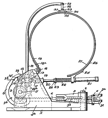
The present invention relates to clutch pulleys, particularly to those of the type having a clutch for coupling the pulley directly to the drive shaft for rotation in one direction, and a reversing gearing controlled by a brake for causing rotation in the opposite direction.
One object of the invention is to simplify the controlling means so that the direct clutch and reversing brake can be alternately thrown in and out by means of a single control lever.
Another object of the invention is to provide a holding brake which will be operated by the same control lever, and will maintain the clutch pulley in any desired position when the direct clutch and reversing brake are both in inoperative position.
Another object of the invention is to provide an improved means for suspending a brake band over a brake drum so that the two will be held out of engagement when the brake band is not tightened The invention will be described in detail in connection with the accompanying drawing in which one embodiment of the same is shown.
Claims:
1. In a device of the kind described, a drive shaft, a pulley, a friction clutch for clutching said pulley directly to said shaft, a differential reversing gear having a brake drum, and a brake band cooperating therewith, means for operating said clutch, and a cam for controlling said brake operable by said clutch operating means, said cam having a neutral position, an eccentric curve on one side of said neutral position for tightening said brake band, and a concentric curve on the other side of said neutral position for permitting the throwing in of said clutch Without affecting said brake.
2. In a device of the kind described a constantly rotating shaft, a pulley rotatably mounted on said shaft, a clutch for coupling said pulley to said shaft, reversing gearing for said pulley, a cam, a clutch operating member connected to said cam, a follower for said cam, and connections between said follower and said reversing gearing for controlling the latter, said cam having a short protruding surface for operating said reversing gearing, and a long even surface for permitting operation of said clutch without effect upon said reversing gearing.
3. In a device of the class described a constantly rotating shaft, a pulley rotatably mounted on said shaft, a clutch for coupling said pulley to said shaft, reversing gearing forsaid pulley, a brake for holding said pulley stationary, a common control for said reversing gearing and said clutch having a reversing position, a clutch operating position, and an intermediate neutral position, and means actuable by said common control in its neutral position for actuating said brake.
4. In a device of the class described a constantly rotating shaft, a pulley rotatably mounted on. said shaft, a clutch for coupling said pulley to said shaft, reversing gearing for said pulley, a brake for holding said pulley stationary, a common control for said reversing gearing and said clutch having a reversing position, a clutch operating position, and an intermediate neutral position, said common control including a rectilinearly movable cam, a member operated by said cam, connections between said member and said brake, and means for adjusting the longitudinal position of said cam, whereby the movement of said member may be timed to coincide with the neutral position of the common control.
|
|