US Patent: 1,929,269
|
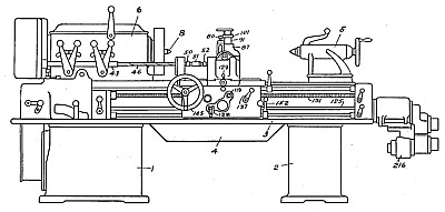
| Apparatus for Automatic Form Turning Lathe
|
|
Patentees:
|
| Clifford A. Bickel (exact or similar names) - Sidney, OH |
| Philber A. Abe (exact or similar names) - Sidney, OH |
| USPTO Classifications: |
| 82/19 |
| Manufacturer: |
| Not known to have been produced |
|
|
Patent Dates:
|
| Applied: |
Dec. 08, 1931 |
| Granted: |
Oct. 03, 1933 |
|
Patent Pictures:
[
1 | 2
]
|
|
|
USPTO (New site tip)
Google Patents
Report data errors or omissions to steward
Joel Havens
Monarch Machine Tool Co. History
"Vintage Machinery" entry for Monarch Machine Tool Co.
|
|
Description: |
| Toulmin & Toulmin - patent attorneys
Our invention relates to an apparatus and method of operation for automatic form turning lathes.
It is the object of our invention to provide an automatic relieving machine and method of operation thereof and method of forming work pieces of various sizes and forms, and particularly forming relieved milling cutters. It is the object of our invention to provide such a machine in which the movement of the tool in imparting the configuration to the work piece by the longitudinal and transverse movements of the tool will be automatically, electrically controlled by the engagement and relative movement of a former pin with respect to a template so that the movement of the former pin will make and break electrical contacts which will, in turn, control the longitudinal and transverse movements of the tool with respect to the work. It is a further object to provide for the continuous spiral cut of the tool with respect to the work without the removal of the tool from the work except as it may be necessary, in the case of forming milling cutters with hooked teeth, to readjust the position of the tool and to compensate its position due to the change in angularity of the gash in the work piece and change in diameter thereof. It is a further object to provide means of continuously and uniformly operating the work piece on the spindle at a uniform speed while automatically in synchronism therewith adjusting the point of application of the tool as the tool progresses longitudinally of the work piece so that the tool will always, Upon its return to the work piece, be applied to the leading edge of the tooth being cut, while, at the same time, the path of cutting from beginning to end of the work piece will be substantially spiral and otherwise continuous, as it is possible by the very delicate and minute adjustment of the electrical controls to maintain the tool in substantially continuous contact with a movement of not over a thousandth of an inch with the work piece so that a spiral cut can be attained, while, heretofore, the best that could be accomplished in the art was a series of substantially parallel, continuous, circular cuts. It is a further object to provide a mechanism and method by which, when the pin once engages with the former, it will remain in engagement with the former continuously until the work is completed. It is a further object to provide means by which, when a hooked tooth work piece is being relieved, to either use a corrected template or a tilted template. In the event the corrected template is used, which we prefer and which is one of the forms of our invention, the template is not of the precise form of the work piece, but. is so corrected that the pin following such a template will control the application of the tool to compensate in an overhanging hooked cutter for the angular loss of position due to the angularity of the gash in the work piece as the tool progresses along the work piece longitudinally so that the tool, when guided by the corrected template, will always apply itself to the leading edge of each tooth no matter what position in the length of the work piece, so that the tool will be immediately applied in cutting position to the leading edge of such tooth irrespective of the change of angularity of the gash which forms one wall of the tooth of the work piece and compensate for the change in diameter. It is our object to eliminate relative movements between the former and former pin at intervals, which has heretofore been the custom in the art, and to thereby secure a cleaner, more uniform cut and one of very much greater accuracy than has heretofore been possible in form turning and relieving machines. It is our object to avoid all use of forming tools and to form the work by rough cutting on my machine and then finish cutting but all cutting to be done in accordance with the method and apparatus we set forth in this document. It is a further object to provide a tracer or former pin slightly larger, usually from ten to eleven thousandths of an inch, than the tool diameter to compensate for the air gap in the electrical contact points in the electrical control switch which controls the magnetic clutches and motors for imparting longitudinal and transverse movement to the tool to cause it to be applied to the work to give the work the desired configuration. It is our object to eliminate the use of a template of the same form as the work when working on a hooked tooth milling cutter, as the use of such a template leads to inaccuracies and complication in the mechanism, which we can avoid by our mechanism and method of cutting. It is our object to provide constant spindle speed and synchronous relieving of the tool, the movements of which, while constant in length, are timed as the carriage progresses according to the spiral of the teeth on the cutter.
|
|

)
)