US Patent: 2,123,788
|
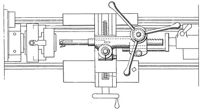
| Key Seating Attachment for Lathes
|
|
Patentee:
|
|
| Don A. McNaughton (exact or similar names) - Knoxville, TN |
| Manufacturer: |
| Not known to have been produced |
|
|
Patent Dates:
|
| Applied: |
Mar. 06, 1937 |
| Granted: |
Jul. 12, 1938 |
USPTO (New site tip)
Google Patents
Report data errors or omissions to steward
Joel Havens
|
|
Description: |
| Byrns, Kehr & Swecker - patent attorneys
This invention relates to an improvement in key-seating attachments for lathes, for cutting a key-way or key-seat in work bored or chucked in a machine before removal from the lathe. Heretofore, the only method employed for cutting a key-seat in work in a lathe was to "pump" or hand-crank the carriage of the lathe back and forth, while the spindle and the work were held from rotation, using a boring tool, having a cutter set to cut as it was forced into the work. While this has been done in emergencies, it is not practical because on small lathes the feed-gearing and slide-rest are too light and on large lathes the carriage is too hard to move. In either case, the carriage binds and requires much power to overcome this binding. This is because the cutter is positioned near the center of the lathe and several inches above the V-slides, while the power to move it has to be applied through the rack and pinion located in front of the bed and well below the V-slides on which the carriage moves. The object of this invention is to provide a practical and relatively inexpensive attachment which may be applied to the work, while it is held in the lathe for cutting of a key-way therein with the least loss of power and with proper centering of the key-wat cutter bar substantially co-incident with the center of the lathe spindle. The cutter bar has provision for practical and effective reciprocation thereof, while the cutter is fed into work on the usual rest on the lathe. An abutment takes the end thrust of the attachment on the cutting stroke. The cutter bar has a cutter connected therewith, so as to be relieved automatically on the back stoke or idle stroke of the cutter bar, and this connection also permits ready detachment of the cutter from the cutter bar, as when it is desirable to substitute another cutter or a cutter of a different with therefor. |
|