US Patent: 2,224,531
|
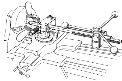
| Metalworking Attachment for Lathes
|
|
Patentee:
|
|
| Hubbard H. Winegar (exact or similar names) - Palatka, FL |
| Manufacturer: |
| Not known to have been produced |
|
|
Patent Dates:
|
| Applied: |
Mar. 20, 1940 |
| Granted: |
Dec. 10, 1940 |
USPTO (New site tip)
Google Patents
Report data errors or omissions to steward
Joel Havens
|
|
Description: |
| Smith, Mitchael & Gardner - patent attorneys
My invention relates to a metalworking attachment for lathes, and has particular reference to a device adapted for ready attachment to and removal from the cross-slide of a standard or conventional lathe after the usual too post of the lathe has been removed therefrom, and is primarily designed for use in cutting or planing an interior groove or key-way in the hub of a propeller, gear, pulley, wheel or the like. It is an object of my invention to provide a relatively simple and highly efficient metalworking attachment for lathes, which attachment may be readily mounted on the cross-slide of a standard or conventional lathe after the ordinary tool-post has been temporarily removed from the lathe, and which attachment includes a novel means for mounting a reciprocable cutter bar in proper angular position for cutting an interior groove or key-way in the straight or tapered bore of the hub of a propeller, gear, or other work piece mounted in the chuck of the lathe. It is an object of my invention to provide a device of the above mentioned character including a reciprocable cutter bar having at its forward end a cutter, and to so mount the cutter bar that during the forward stroke thereof the cutter acts on the work .piece to cut or plane the groove or key-way and during its return or backward stroke is automatically rocked about its mounting to relieve the cutter from contact with the work piece. It is an object of my invention to provide a device of the above mentioned character including a reciprocable cutter bar having at its forward end a cutter, and to provide a pivotally mounted supporting block for said cutter bar and-through which the said cutter bar is reciprocated, the said block cooperating with stops which limit its pivotal movement to retain the cutter in contact with the work piece during the forward movements of the cutter bar but which permit the block to pivot to a limited extent to relieve the cutter tram contact with the work piece during the return or backward stroke of the cutter bar. It is a further object of my invention to provide a device of the above mentioned character including a pivotally mounted-supporting block for the reciprocating cutter bar, which block partakes of limited pivotal movements about a vertical axis as the cutter bar is moved longitudinally into and out of contact with the work piece, whereby the cutter carried by the bar contacts the work piece as the cutter bar is moved into the bore of the work piece to cut or plane the groove or key-way therein and is relieved from contact with the work piece as the cutter bar is moved out of the bore of the work piece, the movements of said block and the cutter bar carried thereby being effected automatically-upon actuation of the mechanism which moves the cutter bar into and out of the bore of the work piece. It is a further object of my invention to provide a device of the above mentioned character in which the block may be locked against-pivotal movement when the groove or key-way cutting bar is removed from the attachment-and is replaced by a conventional boring tool or the like. It is a still further object of my invention to provide a device of the above mentioned character wherein the reciprocating cutter bar is slidably mounted in a relatively heavy guide-bar which is longitudinally adjustable within the supporting block and which may be clamped in various positions therein, so that the cross-slide of the lathe, the supporting block and the end of the guide-bar carrying the cutter may be placed closely adjacent the work piece mounted in the chuck of the lathe and the cutter bar projected a minimum distance beyond the end of the guide bar to-bring-the cutter into contact with the work piece during the groove or key-way cutting or planing operation, whereby the go cutter bar is rigidly supported adjacent the work piece and the tendency of the cutter bar to bend and/or "chatter" is definitely eliminated.
|
|