US Patent: 334,770
|
| Micrometer Gage
|
|
Patentee:
|
|
| George B. Grant (exact or similar names) - Malden, MA |
| Manufacturer: |
| Not known to have been produced |
|
|
Patent Dates:
|
| Applied: |
Jul. 27, 1885 |
| Granted: |
Jan. 26, 1886 |
USPTO (New site tip)
Google Patents
Report data errors or omissions to steward
Joel Havens
|
|
Description: |
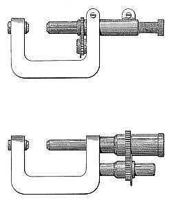
| This invention relates to micrometer-calipers; and it consists, principally, in providing a second reading scale by which the measurements are indicated in eighths, thirty-seconds, and sixty-fourths of an inch, in addition to the usual scale to tenths, hundredths and thousandths of an inch. It consists, also, in a novel arrangement of the scales and indices, which simplifies the construction of the instrument, and in a double clamp for holding the measuring-pin. Figure 1 shows the whole invention, and Fig. 2 shows a second and equivalent arrangement of some of its parts. I prefer the arrangement shown by Fig. 1, where the measuring-pin c has two linear scales upon it, one scale, being graduated to thirty-seconds, and the other scale, Z, as usual, to fortieths, of an inch. The whole number of thirty-seconds or fortieths is read off on these linear scales at an index-edge, d, in this case the edge of the ring e. The fractional parts of the decimal scale b are read off on the ring-scale u at the index-point t, while the fractional parts of the scale of thirty-second are read on the ring-scale h at the index s. The ring e has a gear, w, and the ring h a gear, x, and these gears have numbers of teeth in the proportion of thirty-two teeth on w to forty teeth on x, or in the proportion of the graduations of the. linear scales, whatever that may be. The ring h is held in place by the screw-head, and the ring e must be held by suitable means such as the groove and the flange g. The frame o is split, so that the clamping-jaws and screw j hold the pin o firmly at its unthreaded end and may be set up to lock it or hold it fast when desired. The tension of the nut z is regulated by the clamping screws and jaws. The measuring-pin c is threaded at its outer end, I, and bears a milled head, T, by which it is turned. The frame o and the anvil or stop n are of the ordinary form.
|
|