GB Patent: GB-354,386
|
| Multiple Spindle Drilling And Like Machines
|
|
Patentees:
|
| George Adcock (exact or similar names) - Leicester, England |
| Howard Shipley (exact or similar names) - Leicester, England |
|
|
Patent Dates:
|
| Applied: |
May 10, 1930 |
| Granted: |
Aug. 10, 1931 |
Espacenet patent
Report data errors or omissions to steward
Joel Havens
"Vintage Machinery" entry for Adcock & Shipley Ltd.
|
|
Description: |
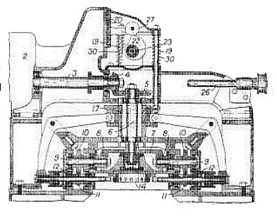
| In a multiple spindle drilling or like machine, the tool spindles are fed towards and away from the work by means of a slidable grooved collar, concentric with the main driving shaft, which controls bell-crank levers connected to the spindles. The driving shaft 3 of an electric motor 2, Fig. 1, rotates, by means of bevel gears 4, 5, 7, 8, lay shafts 9 which drive the drill spindles 12 through spur wheels 10, 11. Concentric with the vertical driving shaft 6 is a grooved collar 17 which is rigidly connected by rods 19 to a slide 20, normally forced downwards by extension springs 30; a cam 22 fixed to a shaft 23, which is driven by a worm and worm wheel 25, 24 from a secondary shaft 26, imparts a uniform feed and quick return to the tool spindles by contacting with a roller 27 attached to the slide 20. A number of bell-crank levers are rotated by the movement of the collar 17 and simultaneously feed the drill spindles ; allowance is made for the vertical movement of the ends 37 of the levers by providing pivoted blocks 40, Fig. 2, which move in vertical grooves 41 in collars 42 attached to the spindles. Feed of the spindles is automatically stopped by arranging a clutch device, Fig. 3, to uncouple the worm wheel 24 from the cam shaft 23. A bar 45 having a limited movement in a transverse boring of the cam shaft 23 is provided with a groove 48 into which a spring- pressed ball 49 seats when the clutch element 44 is uncoupled from the worm wheel; the bar 45 is manually set and rotates with the cam shaft and worm wheel until a conical catch 50 on the bar contacts with an adjustable stop 51 mounted on the fixed face-plate 52. The tool spindles may also be arranged with their axes inclined or parallel and the whole machine may be bodily reversed so that the work may be more easily introduced and removed from the jig 14. |
|