US Patent: 400,550
|
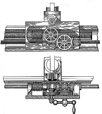
| Turning Lathe
|
|
Patentee:
|
|
| Robert F. Darling (exact or similar names) - Seneca Falls, Seneca County, NY |
| Manufacturer: |
| Not known to have been produced |
|
|
Patent Dates:
|
| Applied: |
Jul. 31, 1888 |
| Granted: |
Apr. 02, 1889 |
USPTO (New site tip)
Google Patents
Report data errors or omissions to steward
Joel Havens
|
|
Description: |
| F. F. Warner - patent attorney
What I claim as new, and desire to secure by Letters Patent, is:
1. The combination, in the longitudinal feed mechanism of a lathe, of a short or comparatively short rotary screw, worm, or spiral turning in suitable bearings extending from the carriage, and a long or comparatively long rack engaging the said screw and secured to the frame orbed of the lathe, substantially as and for the purpose specified.
2. The combination, in the longitudinal feed mechanism of a lathe, of a short or comparatively short screw, worm, or spiral turning in suitable bearings extending from the carriage, a long or comparatively long rack engaging the said screw and secured to the frame or bed of the lathe, and shifting-gear 5 constituting a part of the longitudinal-feed mechanism and arranged to engage alternately a gear or pinion on the shaft or spindle of the said worm and a pinion or gear in the cross-feed mechanism, substantially as and for the purpose specified.
3. In the feed mechanism of a lathe, the herein before-described means for reversing the feed-movement, the said means consisting of the shaft A', the bevel-gears B' B', turning loosely on the said shaft and having, clutch engaging, teeth, the sliding clutch C', mounted on and turning with the said shaft and arranged between the said, gears, the wheel or gear U', engaging the said bevel-gears, an arm for shifting the said clutch, and the apron of the lathe, substantially as and for the purpose specified.
4. A lathe in movement and the cross-feed movement are produced independently by means of a shifting-gear in continuous engagement with driving-gear constituting a part of the means for producing both the said movements, and alternately in engagement with the gear directly employed for moving the carriage and the gear for moving the tool-block, substantially as and for the purpose specified.
5. A rack made in sections arranged end to end in a line and having an inwardly-curved outer face on which are inclined alternate which the longitudinal-feed grooves and ribs, in combination with the frame or bed of a lathe and the carriage-moving mechanism, substantially as and for the purpose specified.
6. A lathe in which the longitudinal-feed gearing and the cross-feed gearing are combined with supplemental-feed gearing for simultaneously operating the longitudinal-feed gear and the cross-feed gear, substantially as and for the purpose specified.
7. The combination, in a lathe, of the wheel D, constituting a part of the cross-feed gearing, the gears H' and I' and their shaft, the gear E', having thereon one or more sets of teeth, e e, the latter being in operative engagement with the wheel D through the medium of the gears H' and I', and the longitudinal-feed gearing, substantially as and for the purpose specified.
8. The combination, in a lathe, of the wheel D, constituting a part of the cross-feed gearing, the gears H' and I' and their shifting shaft F', the gear E', having thereon one or more sets of teeth, e' e', the latter being in operative engagement with the wheel D through the medium of the gears H' and I', and the longitudinal-feed gearing, substantially as and for the purpose specified. |
|