US Patent: 56,164
|
Turning Lathe Tool
Improved Tool for Adjusting Lathes to Turn Tapered Shafts
|
|
Patentee:
|
|
| William N. Bereley (exact or similar names) - Cedar Rapids, IA |
| Manufacturer: |
| Not known to have been produced |
|
|
Patent Dates:
|
| Granted: |
Jul. 10, 1866 |
USPTO (New site tip)
Google Patents
Report data errors or omissions to steward
Joel Havens
|
|
Description: |
| Coburn & Watts - patent attorneys
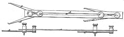
A represents a strip or plate of metal, of any suitable length, provided with a longitudinal slot, as shown, (marked a.) B B and C C represent, respectively, pairs of arms pivoted together at one end at D D by a screw passing through the aforesaid slot a, by the turning of a nut, upon which said arms may be adjusted and secured in any desired position. E represents screws passing through said slot, between the arms B B and C C, as shown, having suitable cylindrical blocks thereupon, against which the arms aforesaid may rest, thus insuring the symmetrical adjustment of the arms upon each side of the plate A. Having described the construction of my invention, I will now describe the manner in which it is used in adjusting the lathe as said. F G represent the devices for holding the shaft to be operated upon, (marked H,) one of them, G, having a lateral adjustment when desired. The shaft having been arranged in the lathe, a line is described upon the top thereof, as shown at d, in the same vertical plane with the points F G- supporting the shaft. The tool is then adjusted so that the distance between the points & of the arms B shall equal the diameter of the larger end of the proposed tapering shaft, and the point o of the arms C shall in like manner measure the diameter of the smaller end of said shaft, while the distance between the points 6 and c represents the proposed length of the shaft. A straight-edge, I, is then arranged parallel to the line d, before mentioned, at a suitable distance therefrom, being attached in some suitable manner to the tool-carriage of the lathe, when my invention, adjusted as aforesaid, is arranged against the said straight-edge, as shown. The adjustable bearing Gr is then moved toward the tool until the shaft is brought to the position indicated by the dotted line, when it is properly adjusted, and the turning process will produce a shaft of the required-shape. |
|