US Patent: 595,475
|
| Measuring Pole
|
|
Patentee:
|
|
| Reuben Hegarty (exact or similar names) - Madera, Clearfield County, PA |
| Manufacturer: |
| Not known to have been produced |
|
|
Patent Dates:
|
| Applied: |
Apr. 30, 1897 |
| Granted: |
Dec. 14, 1897 |
USPTO (New site tip)
Google Patents
Report data errors or omissions to steward
Joel Havens
|
|
Description: |
| John Wedderburn, patent attorney
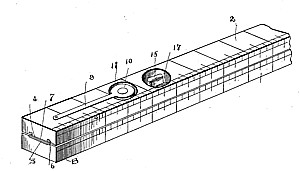
This invention is an improvement in lineal measures, and especially in poles or rods which are made extensible longitudinally. My improved measuring-pole is hereinafter described, and the novel features are specifically indicated. In the accompanying drawings, forming part of this specification, Figure 1 is a perspective view of a portion of a measuring pole constructed in accordance with this invention. Fig. 2 is a longitudinal section. Fig. 3 is a cross-section; and Figs. 4 and 5 are cross-sections, on an enlarged scale, of the two sections of the measuring-pole.
I construct my improved measuring pole of longitudinal sections or members, which are so connected as to be adapted to slide one on another and which have no projecting parts. In the drawings, 1 and 2 indicate the members of the pole, which are generally rectangular in cross-section, and therefore when secured together present also a rectangular figure. These sections or members of the pole are held together against lateral play, but capable of longitudinal movement, by means of a guide 3 upon member 1 and a slide 4 upon member 2. The slide and guide are so made that when they co-act the adjacent faces of the members are in contact with each other, as shown, to present not only a finished device, but to prevent the entrance of dirt or particles between the sliding poles of the two members. In the particular construction illustrated the face of the member 1 is provided with a longitudinal groove 5, in which the guide 3 is situated, said guide consisting, preferably, of a sheet-metal piece having overhanging flanges 6 in the manner shown. In the particular construction illustrated these overhanging flanges 6 of the guide stand slightly beyond the face of the member 1, as shown. The member 2, upon which the slide 4 is secured, is provided with a central rib 7 on its inner face, which stands a little beyond the edges of the member. On each side of this rib 7 are grooves 8, while the slide 4, which consists of a strip of sheet metal, is secured upon its rib and projects over the grooves 8 and almost to the outer sides thereof. In this way it is seen that between the outer edges of the slide 4 and the grooves a pocket is formed, which receives the flanges 6 of the guide. These parts are so made that a close and tight fit is secured, which holds the two members of the pole together and in the position illustrated, and while relative lateral movement is effectually prevented, the parts can move longitudinally, as is obvious. For holding the members rigid with relation to each other, I employ a spring-actuated detent 9, that is situated within a suitable recess 10 in said member 2. This detent is pivoted between its ends and lies entirely within the recess, that is to say, there are no parts which project beyond the face of the member 2. One end of this detent is provided with a finger-piece 11, beneath which 80 the spring 12 is situated, while the other end of the detent carries a pin 13, that extends through an opening in the slide 4. The guide 3 is provided with a series of openings 14 to receive said pin 13 and thus hold the members with relation to each other. Of course the distance between the openings 14 can vary as desired, while, for instance, it may be one foot. Devices are also provided for holding the members at any other point, which consists of a thumb-screw 15, passing through a screw-threaded opening 16 in the member 2 and through the slide 4,while the head of the thumb-screw is situated in a recess 17 in said member. By means of this thumb-screw the two members can be wedged together at any point. |
|