US Patent: 731,001
|
| Explosion Engine
|
|
Patentee:
|
|
| Edward E. Williams (exact or similar names) - Dayton, Montgomery County, OH |
|
|
Patent Dates:
|
| Applied: |
Nov. 07, 1901 |
| Granted: |
Jun. 16, 1903 |
USPTO (New site tip)
Google Patents
Report data errors or omissions to steward
Joel Havens
"Vintage Machinery" entry for W. P. Callahan Co.
|
|
Description: |
| Abstract:
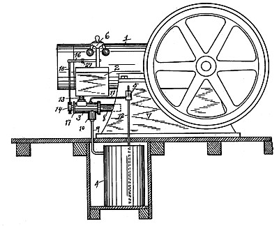
This invention relates to new and useful improvements in explosive-engines and has particular reference to the means for and manner of admitting the liquid fuel such, for example, as gasolene and air-to the vaporizing-chamber.
The object of the invention is to obtain a uniform speed of the engine when using a liquid fuel regardless of the load. A constant supply of gasolene or liquid fuel is made to' pass through a vaporizing-chamber in a constant body or volume sufficient to supply a proper mixture for a maximum load. In other words, the volume of gasolene, which passes through the vaporizing-chamber, is sufficient to supply fuel to the engine under the heaviest load at which the said engine is run.
Claims:
1. In an explosive-engine, the combination with the mixture-feed pipe for the engine, of a vaporizing-chamber having at the bottom a liquid receiving and outlet trap, and at one side above the plane of said trap a horizontally offset ported valve-casing in communication with the mixture-feed pipe, a controlling-valve arranged within said casing, an oil-feed pipe pendent vertically within the vaporizing-chamber from the top thereof and delivering into the bottom receiving and outlet trap, and an air-induction pipe in communication with the vaporizing-chamber at one side thereof and in the horizontal plane of the ported valve-casing, said air-induction pipe delivering a supply of air into the vaporizing-chamber and across the stream of oil falling into said trap, substantially as set forth.
2. In an explosive-engine, the combination with the mixture-feed pipe for the engine, of a vaporizing-chamber having at the bottom a liquid receiving and outlet trap and at one side a horizontally-offset cylindrical valve-casing having a ported portion in communication with the mixture-feed pipe, a horizontal tubular ported controlling-valve fitting within the cylindrical valve-casing and having its open end communicating directly with the vaporizing-chamber, an oil-feed pipe pendent within the vaporizing-chamber from the top thereof and discharging into said trap, and an air-induction pipe communicating through one side of the vaporizing-chamber in the horizontal plane of the tubular valve and at right angles to the plane of the oil-feed pipe.
|
|