US Patent: 737,686
|
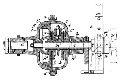
| Reversing Gear
|
|
Patentee:
|
|
| Carl W. Weiss (exact or similar names) - New York, NY |
| Manufacturer: |
| Not known to have been produced |
|
|
Patent Dates:
|
| Applied: |
Jul. 18, 1903 |
| Granted: |
Sep. 01, 1903 |
USPTO (New site tip)
Google Patents
Report data errors or omissions to steward
Joel Havens
"Vintage Machinery" entry for Weiss Engine Co.
Carl W. Weiss-The Dean of oil engineers.
|
|
Description: |
| Abstract:
The object of this invention is to produce a reversing-gear which shall be compact, simple in construction, free from liability to stripping of the teeth through sudden engagement of the parts, and shall require but slight movement in either direction to effect engagement or disengagement.
The improved gear can be applied easily to shafts, which are in alignment, and is particularly advantageous for marine use, since the pressure upon the parts which are in frictional engagement will be increased by the thrust of the propeller-shaft both in going ahead and in going a stern.
Claims:
l. A reversing-gear comprising a frame or casing, a clutch member arranged within said frame or casing, a sleeve projected within said frame or easing, means to hold said sleeve from rotation, a transmission-pinion carried by said sleeve, freely-rotatable gears for engagement with said pinion and adapted for frictional engagement with said casing and said clutch member respectively, and means for disengaging said clutch member from said frame or casing and for effecting engagement -between said gears and said clutch member and said casing respectively, substantially as described.
2. The combination of a frame or casing, a clutch member arranged within said frame or casing, independent shafts to which said parts are respectively connected, a stationary transmission pinion, oppositely disposed transmission-gears for engagement with said pinion and adapted for friction al engagement with said clutch member and said frame or casing respectively, and means for effecting disengagement of said clutch member from said frame or casing and for effecting frictional engagement between said gears and said clutch member and said frame or casing respectively, substantially as described.
3. The combination of a frame or casing, a clutch member arranged within said frame or casing, independent shafts to which said parts are respectively connected, a non-rotatable sleeve mounted upon one of said shafts, a transmission-pinion carried by said sleeve, transmission-gears mounted loosely upon said sleeve, for engagement with said pinion and adapted for frictional engagement with said clutch member and said frame or casing and means for effecting disengagement of said clutch member from said frame or casing and for effecting frictional engagement between said gears and said clutch member and said frame or casing respectively, substantially as described.
4. The combination of a frame or casing, independent shafts one of which is movable longitudinally, a clutch member mounted upon said longitudinal shaft within the shell` or casing, a non-rotatable sleeve mounted upon said shaft and movable longitudinally therewith, a transmission-pinion carried by said sleeve, transmission gears mounted loosely on said sleeve for engagement with said pinion and adapted for frictional engagement with said clutch member and said frame or casing, and means to shift said shaft longitudinally, substantially as described.
|
|