US Patent: 781,003
|
| Truck
|
|
Patentee:
|
|
| Britain Holmes (exact or similar names) - Buffalo, NY |
| Manufacturer: |
| Not known to have been produced |
|
|
Patent Dates:
|
| Applied: |
May 31, 1904 |
| Granted: |
Jan. 31, 1905 |
USPTO (New site tip)
Google Patents
Report data errors or omissions to steward
Joel Havens
|
|
Description: |
| A. J. Sangster - patent attorney
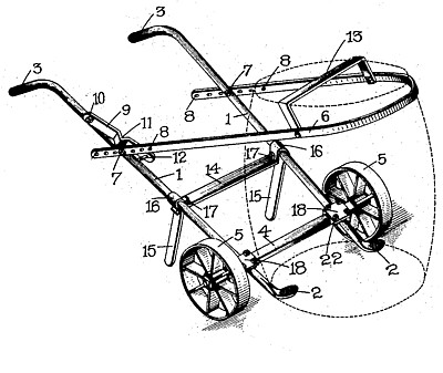
This invention relates to an improved truck for moving heavy barrels; and it comprises in part two members having their lower extremities shaped to be forced beneath a barrel and a loop adapted to encircle the upper portion of a barrel to hold it in upright position. The object of the invention is to provide a simple, cheap, comparatively light, and very strong device for quickly and conveniently picking up and moving heavy barrels and the like without tipping or tilting them on their side. The truck is designed especially for the extremely rapid handling of heavy sugar-barrels and the like.
I claim as my invention;
1. A truck comprising two side members having flattened lower ends adapted to be forced beneath a barrel, and bent upper ends constituting handles, a cross-bar, wheels journaled on said cross-bar, a loop pivoted to the side members and adapted to encircle a barrel to retain it in upright position and a bar extending across the loop and adapted to engage the barrel-top to limit the downward movement of the loop.
2. A truck comprising two side members having flattened lower ends adapted to be forced beneath a barrel, and bent upper ends constituting handles, a cross-bar, wheels journaled on said cross-bar, a loop pivoted to the side members and adapted to encircle a barrel to retain it in upright position and a U-shaped bar extending across the loop and adapted to engage the barrel-top to limit the downward movement of the loop.
3. A truck comprising two side members having flattened lower ends adapted to be forced beneath a barrel and bent upper ends constituting handles, a cross-bar, wheels journaled on said cross-bar, a loop pivoted to the side members and adapted to encircle a barrel to retain it in upright position and a spring locking-arm fastened to one of the side members for normally holding the loop in elevated position, substantially as set forth.
4. A truck comprising two side members having flattened lower ends adapted to be forced beneath a barrel and bent upper ends constituting handles, a cross-bar, wheels journaled on said cross-bar, a loop pivoted to the side members and adapted to encircle a barrel to retain it in upright position and a spring locking-arm fastened to one of the side members for normally holding the loop in elevated position; said locking-arm having a U-shaped bend, substantially as set forth.
5. A truck comprising two side members having flattened lower ends adapted to be forced beneath a barrel and bent upper ends constituting handles, a cross-bar, wheels journaled on said cross-bar, a loop pivoted to the side members and adapted to encircle a barrel to retain it in upright position and a spring locking-arm fastened to one of the side members for normally holding the loop in elevated position; said locking-arm having a U-shaped bend and a laterally projecting stop, substantially as set forth.
6. A truck comprising two side members having flattened lower ends adapted to be to forced beneath a barrel and bent upper ends constituting handles, a cross-bar, wheels journaled on said cross-bar, a loop pivoted to the side members and adapted to encircle a barrel to retain it in upright position; said loop having a plurality of holes in its ends and bolts passed through any one of said holes for adjustably securing the loop to the side members, substantially as set forth..
7. A truck including two side members, a cross-bar connecting said members, supporting legs depending from said cross-bar, the cross-bar and supporting legs being integral, integral U-shaped bends formed at the junction of the cross-bar and supporting-legs which partially encircle the side members and bolts for clamping the U-shaped bends around said side members.
8. A truck including two side members, a cross-bar connecting said members, supporting legs depending from said cross-bar; the cross-bar and supporting legs being integral, integral U-shaped bends formed at the junction of the cross-bar and supporting-legs which partially encircle the side members and bolts extending through the extremities of the U-shaped bends and beneath the side members for clamping the U-shaped bends around said side members.
|
|