US Patent: 848,190
|
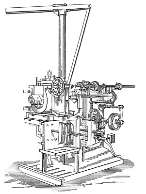
| Shaper for Crowning and Finishing Driving Boxes on Locomotives, &c.
|
|
Patentees:
|
| Matthew Morton (exact or similar names) - Muskegon, Muskegon County, MI |
| Henry E. Morton (exact or similar names) - Muskegon, Muskegon County, MI |
| Manufacturer: |
| Not known to have been produced |
|
|
Patent Dates:
|
| Applied: |
May 15, 1905 |
| Granted: |
Mar. 26, 1907 |
USPTO (New site tip)
Google Patents
Report data errors or omissions to steward
Joel Havens
"Vintage Machinery" entry for Morton Mfg. Co.
|
|
Description: |
| Newell S. Wright, patent attorney
Our invention is designed to provide a shaper or planer adapted for various kinds of work, the same being particularly fitted, for example, for crowning and finishing the driving-boxes of locomotives, including the planing of the exterior surfaces of said boxes.
What we claim as our invention is:
1. In a draw-cut shaper the combination of a hollow reciprocatory ram, a hollow arbor there within adapted to be rotated, a removable head engaged in one end of the arbor and projecting forward of the ram and rotatable with the arbor, a rod extending through the arbor engaged with said head to longitudinally adjust the head in the arbor, and means engaging the opposite end of the rod to longitudinally adjust the rod in the arbor.
2. In a draw-cut shaper the combination of a hollow reciprocatory ram, a hollow arbor there within adapted to be rotated and provided at one end thereof with a tapered recess, a removable head rotatable with the arbor provided with a tapered shank to fit into the corresponding recess of the arbor, a separately-constructed tool-holder engaged in said head, an adjusting-rod extending through the arbor and engaging said head, and means engaging the opposite end of the rod to draw the rod longitudinally of the arbor.
3. In a draw-cut shaper the combination of a hollow reciprocatory ram, a hollow arbor there within adapted to be rotated, a removable head engaged in one end of the arbor and rotatable therewith, an adjusting-rod passing through said arbor engaged at one end with said head, a separately-constructed tool-holder engaged in said head, and means engaging the opposite end of the rod to longitudinally adjust said head in said arbor.
4. In a draw-cut shaper the combination of a hollow reciprocatory ram, a hollow arbor there within adapted to be automatically rotated provided with a conical recess in one end thereof extending longitudinally of the arbor, a removable head provided with a conical shank engaged in the recessed end of the arbor, a separately-constructed tool holder engaged in said head, and adjusting mechanism to tighten the shank of said head in the recess of said arbor, whereby the head and the arbor will be simultaneously rotated.
5. In a draw-cut shaper the combination of a rotatable head, a tool-holder engaged with said head, a tool in said holder, said head provided with a hub projecting forward of the tool-holder, and index mechanism engageable upon said hub for setting said cutting-tool.
6. In a draw-cut shaper the combination of a rotatable head, a tool-holder engaged with said head, a tool in said holder, said head provided with a hub projecting forward of the tool-holder, and index mechanism removably engaged upon said hub and projecting under the lower end of the cutting-tool to set the cutting-tool.
7. In a draw-cut shaper the combination of a chambered rotatable head, a separately constructed tool-holder pivotally engaged in the chamber in said head provided with a separately-constructed supplementary slotted holder extending lengthwise there through, and a cutting-tool engaged in the slot of the, supplementary holder to rotate circumferentially together with the head, the slot of the supplementary holder extending there through at an acute angle to the perpendicular to hold the cutting-tool, whereby the cutting-tool may be set to cut to the right or to the left of the longitudinal center of the head at the will of the operator.
8. In a draw-cut shaper the combination of a reciprocatory ram, a tool-holder engaged with said head, said head provided with a hub projecting forward of the tool-holder, a depending arm provided with a scale removably engaged upon said hub, a bracket vertically adjustable upon said arm and extending underneath the cutting-tool, and a micrometer-screw carried by said bracket for adjusting the position of the cutting-tool.
9. In a draw-cut shaper the combination of an arbor, a head engaged in said arbor, a tool-holder pivotally engaged in said head to oscillate longitudinally of the head, an interchangeable supplementary holder engaged in said head provided with an upright slot, and a cutting-tool engaged in the slot of the supplementary holder, whereby the cutting-tool will relieve from the work on its return stroke. |
|