US Patent: 98,423
|
| Lathe
|
|
Patentee:
|
|
| William Sellers (exact or similar names) - Philadelphia, PA |
| Manufacturer: |
| Not known to have been produced |
|
|
Patent Dates:
|
| Granted: |
Dec. 28, 1869 |
USPTO (New site tip)
Google Patents
Report data errors or omissions to steward
Joel Havens
|
|
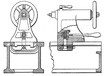
Description: |
| My invention relates to the class of lathes in which the tool slide or saddle rests upon flat top surfaces of the shear, and is held down and guided in its sliding movements by gibs under the beveled edges of the shear. The adjustable heads of such lathes, as ordinarily constructed, are so guided within the sides of the shear as to make the relative accuracy of the centers of the lathe dependent upon the perfect fitting of the adjustable head within these guiding-surfaces; and if, owing to imperfect fitting in the first place or from gradual wear of these surfaces, any lateral play of the head is permitted within its guiding-surfaces, then the absolute parallelism of the centers is destroyed, and their liability to produce inaccurate work increases in proportion to the inefficiency of the guiding-surfaces. Now, the object of my invention is mainly to provide against these heretofore-existing defects by so arranging the wearing and guiding surfaces of the adjustable head and shear that the line of the centers and accuracy of the work shall not be dependent on the lateral fit of the movable head between the two sides of the shear, but be governed by the contact of surfaces, relatively so disposed that any ordinary wear due to continued use shall not impair the true parallelism of the centers. To this end I provide along the bottom of the inner side of one of the flat top surfaces of the shear an outwardly-beveled projection, and I so arrange the bearing-surfaces of the clamping-piece which holds down the adjustable head that the clamping-pressure is partly brought up against the beveled side of the aforesaid projection on the shear, whereby the head, in addition to being securely held down to its place on the surface of the shear, is drawn over sidewise in the direction of the beveled surface and against the inner vertical edge of that side of the shear. On the other side the head is only held down securely to the shear by the clamp, without any laterally-fitting surface; and it will thus be seen that by this arrangement the defects arising from the ordinary manner of fitting the head between the two sides of the shear are avoided. Another feature of importance in my invention consists in a novel and very efficient construction of the mechanism for actuating the said clamp, whereby the movable head may either be securely held down in any required position or instantly disengaged from its hold on the shear by simply moving a conveniently placed handle in the required direction, and without the use of a separate wrench, the clamping-screw being so adjustable that a limited amount of movement of the lever within the same space may always suffice to tighten or loosen the clamp.
|
|