GB Patent: GB-189,508,990
|
| Machines for Planing Metal
|
|
Patentee:
|
|
| W. Anderson (exact or similar names) - Broadheath, Cheshire, England |
| Manufacturer: |
| Not known to have been produced |
|
|
Patent Dates:
|
| Applied: |
May 07, 1894 |
| Granted: |
Apr. 03, 1895 |
Espacenet patent
Report data errors or omissions to steward
Joel Havens
"Vintage Machinery" entry for George Richards & Co., Ltd.
|
|
Description: |
| Note: Early English patents (pre 1916) were numbered by the year and started at patent #1 at the start of each year in January. The patent # used in DATAMP represents the year of issue and the patent #. This patent is #8,990 of the year 1895.
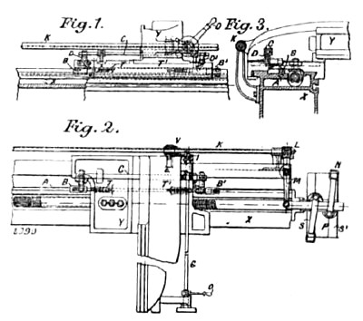
The figures illustrate a side planing machine. A T Slot A extends the full length of the bed X. In this slot are two adjustable stops B, B'. A sliding bar C with rack teeth cut in it is placed on the cutting head or saddle Y. The bar C is actuated by trip levers D, D'. Gearing into the sliding bar C by means of a pinion E is a cross-shaft G, on the front end of which is a feed disc H. On the other end a bevel wheel I serves to drive the bevel pinion V. The back-shaft K has a screw thread L on the end, and works the lever M, which is connected to the strap forks N. On the cross-shaft G is a handle O for starting, reversing and stopping the machine. S and S1 are loose pulleys, running in opposite directions; P is the driving pulley. To start the machine, the cross-shaft G is revolved by means of the handle O; this revolves the back-shaft K about one-eighth of a turn and moves the strap fork N from the pulley S to the pulley P ' The cutting head Y then moves until the trip lever D coined in contact with the stop B. This causes the sliding bar C to revolve the cross-shaft O about one-quarter turn in the opposite direction to that when starting the machine, and so reverses the action, and at the same time puts on the feed by means of the feed disc H. The trip levers D and D' are arranged so that when the sliding bar C, which connects the levers D and D', has moved sufficiently to reverse the machine, the lever D clears the top of the stop B when on the cutting stroke, and the lever D' is brought into position to strike the stop Bl when on the return stroke, and so the action is repeated at each stroke of the cutting head Y. By this arrangement the sliding bar C is at rest immediately the machine is reversed, so that if the momentum of the pulley P should carry the cutting head Y too far, or if a belt should break, the head Y can buffer against the adjustable stop B if on the cutting stroke, or against stop B' if on the return stroke, buffer springs T and T' being fixed on the head Y for that purpose. The cutting head Y can be stopped or reversed at any part of the stroke by revolving the cross-shaft G by means of the handle O.
|
|