GB Patent: GB-745,501
|
| Improvements in Hydraulically Driven Machine Tools
|
|
Patentee:
|
|
| Elton Stiles Cornell (exact or similar names) - East Providence, RI |
| Manufacturer: |
| Not known to have been produced |
|
|
Patent Dates:
|
| Granted: |
Dec. 14, 1953 |
Espacenet patent
Report data errors or omissions to steward
Joel Havens
"Vintage Machinery" entry for Abrasive Machine Tool Co.
|
|
Description: |
| Also patented in the U. S., #2,671,294 and Canada. CA-506,234.
Abstract:
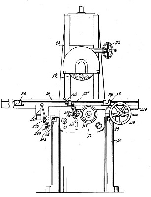
A grinding machine comprises a work carriage 20, Fig. 1, reciprocated by hydraulic means, a hydraulic motor to effect transverse movement of a saddle 16 or, alternatively, of the grinding wheel support, and a single valve 66, Fig. 14, operable between two positions to reverse the carriage 20 and to control the flow of fluid to and from the hydraulic motor, the valve having means in permanently fixed relation thereon whereby pressure fluid is admitted to the hydraulic motor at a predetermined point during each reversal of the carriage 20, is then cut off, and finally, is released. The invention is described with reference to a surface grinding machine in which the grinding wheel is mounted for vertical adjustment by a handwheel 22 on a column 12 and the hydraulic motor effects transverse movement of the saddle 16 which supports the carriage 20 on V-ways. This carriage is connected to a pair of hydraulic rams which are reciprocated by pressure fluid drawn from a reservoir 50 by an electricallydriven constant displacement pump 52 and passed through conduits 56, 74, 76 to the cylinders 42, 44 of the rams, the valves 66 being rotated by adjustable dogs 86, Fig. 1, on the carriage 20 to reverse the fluid flow in the conduits 74, 76 and hence reverse the carriage. Exhaust fluid from the rams passes by way of the valve 66 and conduits 81, 81a to the reservoir 50. The speed of the table is controlled by a manually-rotatable valve 62 interposed between the conduit 56 and the reversing valve 66 and provided with a shaped cross-sectional profile which permits the effective size of a delivery port in the valve casing to be varied. To produce a smooth reversal of the carriage 20, the ports in the valve 66 are shaped to avoid' abrupt changes in flow to the cylinders 42, 44 which are fitted with chambers 42a, 44a to co-operate with tapered grooves 47, 49 on the rams to provide an emergency cushioned stop if the valve 66 fails to operate. At a predetermined point in its rotation the valve 66 permits an unthrottled flow of fluid to pass from the supply conduit 56 to the hydraulic motor by way of a manually slidable valve 120 which determines the direction of fluid flow through the motor and hence the direction of transverse feed. The motor consists of two gears 104, 106 coupled to a feed screw 38 for the saddle 16 and to a clutch 110, 112, Fig. 4, which may be engaged by a hand wheel 116 for manual transverse of the slide when the valve 120 is moved to an intermediate position wherein the inlet and outlet of th hydraulic motor are connected, such engagement being prevented when the valve 120 is in any other position by a gravity-loaded locking pin 140 adapted to co-operate with a notch 148 in the valve stem and a recess 146 in one. of the clutch elements. The feed imparted to the saddle by the hydraulic motor 104, 106 is controlled by a manually adjustable screw 176, Fig. 14, which limits the movement of a spring-loaded piston 168 in a, cylinder 160 connected to the motor exhaust, the outlet from this cylinder being closed by the valve 66 until the transverse feed has been completed when the valve 66 permits the spring-loaded piston 168 to expel the fluid from the cylinder 160 into the exhaust conduit 81a. The piston 168 is provided with shock-absorbing means comprising an auxiliary piston 178 integral with a tapered stem 180 to regulate the effective size of an orifice in the piston 168. To provide a continuous hydraulic transverse feed of the saddle 16, the valve 62 may bedisplaced axially to by-pass the reversing valve 66 and to supply the valve 120 with a continuous and manually controllable flow of pressure fluid. A start and stop valve 186 interposed between the reversing valve 66 and the cylinders 42, 44 and held in the start position against the resistance of a spring may be released by a hand lever 212, Fig. 18, which through a rod 210, and a lever 200, Fig. 14, displaces a spring-loaded latch 190 to permit the valve 186 to move to its stop position in which the conduits 74, 76 are connected together and to an exhaust conduit 81b. The latter communicate with the conduit 81a through a check valve 196 providing a small back pressure to ensure replenishment of leaks from the cylinders 42, 44. Movement of the rod 210 also moves a rod 226, Fig. 18. to a position in which a grooved portion 226' registers with a similar portion on the shaft of a hand wheel 218 so that the latter may be pushed forward to engage a pinion 222 with a rack 224 on the carriage 20 for manual traverse. The shaft carrying the lever 212 also carries an arm 238 for engagement by a dog 240 adjustably clamped to a fixed rail 242 so that traverse of both the table 20 and' the saddle 16 may be automatically stopped at a predetermined position. To prevent the point of reversal of the carriage 20 from varying with its speed, the reversing valve 66 is fitted with a load-and-fire mechanism comprising a cam 90, Fig. 13, and a roller 96 loaded by an adjustable spring 98, the roller serving to accelerate the motor of the cam once it has passed the point 90c. The valve is mounted on roller bearings in the saddle 16 and may be replaced by a sliding valve. A safety valve 57 is included in the hydraulic circuit. |
|