GB Patent: GB-658,590
|
| Tool-holder Attachment for Lathes and Like Machine Tools
|
|
Patentees:
|
| Donald Macpherson Blackburn (exact or similar names) - Johnstone, Renfrewshire County, Scotland |
| John Biggart Lang (exact or similar names) - Johnstone, Renfrewshire County, Scotland |
| Manufacturer: |
| Not known to have been produced |
|
|
Patent Dates:
|
| Applied: |
Jun. 22, 1949 |
| Granted: |
Oct. 10, 1951 |
|
Patent Pictures:
[
1 | 2
]
|
|
|
Espacenet patent
Report data errors or omissions to steward
Joel Havens
"Vintage Machinery" entry for John Lang & Sons
|
|
Description: |
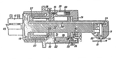
| Abstract:
A copy turning tool-holder attachment for lathes and like machine tools includes a cylinder-and-piston unit adapted to be mounted on a lathe saddle or the like, with the axis of the unit set obliquely to the turning axis of the machine, and is characterized in that the piston component is equipped at one end with the tool-holder proper and at the other end with a control valve device for controlling the leakage of compressed air from the cylinder component by means of a template and follower. The piston component 17 carries at its front end a holder 12 for a tool 23 and is slidable within a cylinder 10 adapted to be secured to the saddle of a lathe. A first piston 18 is provided at the rear end of the piston component and a larger diameter piston 19, open to atmosphere on one side, is provided at the other end. Compressed air is led in at point 22 and this may be released to retract the tool by a hand-operated valve 42. The air supply operates on both faces of piston 18 and passes to forward piston 19 through a duct 28. This latter is also led to an escape orifice 29 controlled by a valve 32 pivoted at 30 and normally held closed by an air bellows 34 supplied from the duct 28. Contact of the lower end 14 of the valve member with a template 15 tilts the valve and allows air to escape until corresponding movement of the piston member restores equilibrium. A further piston member 35 may be provided within an oil-filled cylinder unit 36 to damp out undue movement when the cutting pressure is irregular, a throttling valve 38 being provided to regulate the flow of oil from one side of the piston 35 to the other. |
|

)
)