GB Patent: GB-156,681
|
| Improvements in Scleroscopes
|
|
Patentee:
|
|
| William F. Shore (exact or similar names) - New York, NY |
| Manufacturer: |
| Not known to have been produced |
|
|
Patent Dates:
|
| Applied: |
Jan. 07, 1921 |
| Granted: |
May 08, 1922 |
|
Patent Pictures:
[
1 | 2
]
|
|
|
Espacenet patent
Report data errors or omissions to steward
Joel Havens
"Vintage Machinery" entry for Shore Instrument & Manufacturing Co.
|
|
Description: |
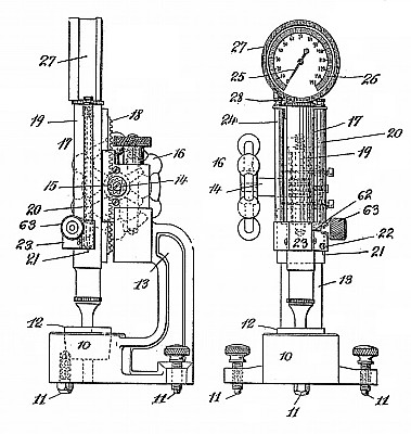
| Abstract:
An impact apparatus comprises a striker, means for lifting the same, means for releasing the striker which impinges on the material and rebounds until arrested at the greatest height of rebound, and mechanical means for indicating the height of rebound which retain the reading until the next test. The main apparatus is contained in a tube 19 having at one side a tube containing a plumb rod, and on the other side a tube containing part of the. indicating gear. The tubes are vertically adjustable on a frame mounted on levelling screws, and to which the anvil is fixed. The tube 19 supports a dial indicator 27 at the top. The striker 31 passes through a guide 35 in a fixed bushing 90, and a hook 30 takes under a shoulder at the end of a recess 32 in the striker. The striker also passes through a movable indicating sleeve 37 and a oneway ball catch device, and is fitted at the lower end with a diamond point or may engage a small supplementary hammer 100. The indicating sleeve 37 carries a rack 38 gearing through a pinion 68 with a rack 69 connected with a rod 72 upon which rests a cross-bar 74 fixed to the rod 29 of the hook 30. The cross-bar is attached to a rack 76 operating a pinion 77 and pointer 25. A spring 36 abuts at the top end against a shoulder on the sleeve 90, and at the lower end against a shoulder on the indicating sleeve 37. The ballcatch device comprises an outer fixed bushing 39 coned at the upper end, and a movable inner sleeve 42 carrying balls 46 which, when the sleeve moves downwards, become jammed against the striker, holding the latter. A pilot sleeve 47 has a shoulder 48 at the lower end which is adapted to engage a shoulder 33 on the striker, the upper end of the sleeve 47 having lugs 49 which pass through slots in the ball-sleeve 42 to be engaged by spring catches 51 pivoted at 52 to the sleeve 37 which is recessed to receive a yoke 53 joining the catches 51. In operation, the material to be tested is placed on the anvil, and the device positioned upon the material. The indicating sleeve is then raised by rack and pinion from a knurled button 63, the spring 36 being compressed. The pilot sleeve 47 rises with the sleeve 37 and carries the striker with it and also moves upwardly the sleeve 42 so that the balls are. disengaged. During this operation the rack 69 and rod 72 are moved downward by rack and pinion gear 38, 68. The cross-piece 74 falls on to the plate 96, and the indicator is brought to zero. When the yoke 53 reaches a spring-catch 59, the catches 51 are tilted and are released from the lugs 49, the striker and pilot sleeve falling together. The latter after the impact engages by means of the lugs 49, the edge 95 of a recess in the sleeve 42 moving the latter down and bringing the balls into .position to catch and join the striker on the beginning of,the next downward movement after the rebound. The sleeve 37 is moved back under the influence of the spring 36 by the knurled head 63,. and during this movement the rods 72 and 29 are raised until the catch 30 engages the ledge at the top of the striker. The needle then indicates the height of rebound. |
|

)
)