GB Patent: GB-304,060
|
| Improvements in Grinding or Abrading Machines
|
|
Patentee:
|
|
| none listed (exact or similar names) - none listed, |
|
|
Patent Dates:
|
| Applied: |
Feb. 23, 1928 |
| Granted: |
Jan. 17, 1929 |
Espacenet patent
Report data errors or omissions to steward
Joel Havens
"Vintage Machinery" entry for Cincinnati Grinders, Inc.
|
|
Description: |
| Abstract:
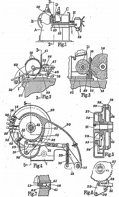
In a grinding machine, the work pieces are presented to opposed grinding and regulating wheels by means of a rotating carrier which steadies the workpieces but allows freedom for their automatic adjustment on the work rest and the periphery of the grinding- wheel. The grinding-wheel 10 has a periperal arcuate groove 11 and the regulating wheel D is mounted on a slide C adjusted by a screw E which is connected by lever mechanism G to a rotary cam 12 to impart reciprocating movement to the regulating wheel in order to feed the blanks to the grinding-wheel. A slide I mounted beneath the slide C carries a bracket 13 provided with a work-rest 14 which projects between the grinding and regulating wheels and supports the spherical heads of the work-pieces 15 during the operation. The grinding-wheel rotates downwardly toward the work-support while the regulating wheel is moved slowly upwardly to rotate the work by frictional contact. The work carrier comprises a disc 23 rotating on a spindle 21 and provided with peripheral openings 24 to receive the shanks of the work-pieces. A plate 25 has a flange 26 which limits the movement of the workpieces into the sockets. Intermittent movement is imparted to the carrier to bring the work-pieces successively into position by means of a ratchet wheel 27 engaged by a pawl 28 which is rocked through lever mechanism, Fig. 4, from a rock shaft 33. The indexing movement is effected at the required time by means of a lug on the cam disc 12, which coacts with a rack rod and pinion to actuate the shaft 33. The cam disc is driven through a belt 43 and worm gearing 42 from a motor 44. The finished work-pieces are ejected by means of a member 46 actuated by an arm 50 on a rock shaft 51. This shaft is operated from a lug 58 on the cam disc 12 through a lever arm 54 and a trigger device. The ejecting movement may force the finished work-piece into a discharge tube 60, whence it may slide out of the machine. In a modification, Fig. 7, the work carrier is fitted with positioning bushes 61 having a portion 62 which fits the shank of the work-piece and a recess 63 to receive the ball end. In this case the ejector forces the ball end into the recess 63, after which the carrier is indexed. When the work-pieces reach the bottom of the carrier they fall out by gravity into a suitable receptacle. |
|