GB Patent: GB-306,710
|
| Improvements Relating to Grinding or Abrading Apparatus
|
|
Patentee:
|
|
| none listed (exact or similar names) - none listed, |
|
|
Patent Dates:
|
| Applied: |
Feb. 25, 1928 |
| Granted: |
Feb. 28, 1929 |
Espacenet patent
Report data errors or omissions to steward
Joel Havens
"Vintage Machinery" entry for Cincinnati Grinders, Inc.
|
|
Description: |
| Abstract:
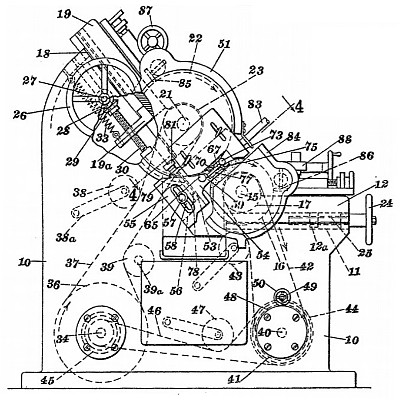
Centreless grinding; guides and rests; trueing rotating tools.-In a centreless grinding machine of the type in which the work is held in contact with the regulating wheel by gravity, means are provided for varying the inclination of the workupporting surface with respect to the operative surface of the regulating wheel so as to vary the pressure of contact between the work and wheel. The machine comprises a bed 10 hollow throughout in order to accommodate some of the driving mechanism, and provided with horizontal ways 11 for a slide 12. Spaced bearings on the slide support the shaft 15 for the regulating wheel 16 which is preferably composed of abrasive such as emery, and between the bearings is the driving pulley 18. Further ways 18, inclined to the horizontal at an angle of about 45 , support a slide 19 which carries the bearings for the shaft 21 of the grinding wheel 22, the driving being by means of a pulley 23. The slide 12 is adjusted by a hand wheel 24 and a screw 25 threaded in the slide, and the slide 19 by a hand wheel 26 connected by bevel gearing 28 to a shaft 30 screwing in the slide. A strong tension spring 33 is arranged to overbalance the weight of the slide 19 slightly in order to eliminate back-lash. The grinding wheel 22 is driven from a main belt-driven shaft 34 through a belt 37 whose tension is maintained throughout the movements of the slide 19 by means of a jockey pulley 38 carried by a pivoted arm 38<a>, and an idle pulley 89 on a fixed shaft engages the tight side of the belt. The regulating wheel 16 is driven by a belt 42, provided with a jockey pulley 43, from a lay shaft 40 which is connected by a belt 46 and cone pulleys 44 to the main shaft 34. A jockey pulley 47 engages the belt 46 and a change speed gear, hand controlled at 50, is interposed between the cone pulley and the shaft 40 so as to rotate the regulating wheel 16 at an adjustable low speed during grinding or at a high speed for trueing by a diamond, &c. A guard 51 attached to the guides 19 concentrically with the wheel 22, has a depending portion 53 inclined to the horizontal at the same angle as the ways 18 and adapted to receive a carrier frame 54, adjustable thereon bv means of a slot 58 and screw 57. An inclined recess 62, Fig. 4, in the carrier 54 receives a wedge 61 whose upper surface is longitudinally horizontal and which is adjusted longitudinally by a manually operated screw 63. The crank support 67 rests on the wedge 61, either directly or with the interposition of a shim 74 so as to vary the inclination of the surface 72 supporting the mesh 73 with respect to the plane of rotation or the regulating wheel 16, the axis of the latter being inclined both horizontally and vertically at angles of about 3 . The support is secured in its adjusted position by means of screws 71 passing through slots 69 therein and into vertical posts 59, 60 formed integrally with the carrier 54. Shims 77, Fig. 1, may be interposed between the support and the posts. The support and carrier are also adjustable transversely by means of the hand operated screw 81, Figs. 1 and 4 which moves the carrier along the surface 53. In its passage through the machine the work 73 is supported before entering the grinding throat and after leaving it by the support 67 and the surfaces 75, 76 of the posts 59 and 60 and during grinding a component of the weight of the mesh acts to keep it in contact with the regulating wheel 16, the directions of rotation of this wheel and the grinding wheel being as' shown by the arrows in Fig. 1. This component of the weight of the work may be varied by adjusting the grinding and regulating wheel slides and also adjusting the height of the support 67 by means of the screw 63, thus causing the position of the work to vary along the surface of the regulating wheel as shown in Fig. 1. The component may also be varied so as to cause the pressure with which the work is urged on the regulating wheel to be less than, equal to, or greater than the weight of the work by varying the inclination of the support 67 in the plane of Fig. 1. This variation mav be produced by the use of shims 82, Fig. 1<a>. The speed at which the work is passed through the machine may be varied by adjusting the longitudinal inclination of the support 67 or by adjusting the speed of rotation of the regulating wheel by the cone pulleys 44. Grinding fluid is supplied as by a valve 83. Fig. 1, and trueing devices 85, 86 are provided for the wheels and are controlled by the mechanisms 87, 88 respectively. |
|