GB Patent: GB-523,022
|
| Improvements in or Relating to Mechanism for Causing Axial Reciprocation of a Rotatable Tool Spindle Such as a Grinding Wheel Spindle
|
|
Patentee:
|
|
| none listed (exact or similar names) - none listed, |
|
|
Patent Dates:
|
| Applied: |
Dec. 22, 1938 |
| Granted: |
Jul. 03, 1940 |
|
Patent Pictures:
[
1 | 2 | 3 | 4
]
|
|
|
Espacenet patent
Report data errors or omissions to steward
Joel Havens
"Vintage Machinery" entry for Cincinnati Grinders, Inc.
|
|
Description: |
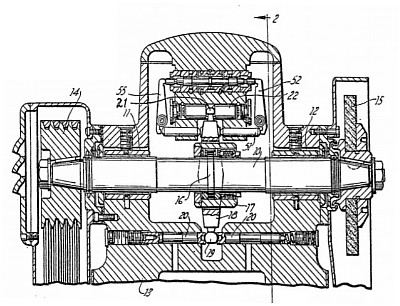
| Abstract:
Mechanism for giving axial reciprocation to a spindle 10 carrying a grinding-wheel 15 includes a piston movable under control of a reversing- valve, which moves under part control of a pilot valve, mounted co-axially with the reversing-valve and actuated by levers coupled to the piston. The spindle 10 has thereon a rib 16 engaged, through antifriction bearings by a sleeve 17 to which is pivoted a lever 18, one end of which is supported in cupped-ended members 20, whilst the other end engages a piston 22. The piston is movable in a cylinder 23, movements of the piston being controlled by valves in a housing 40. The reversing of the piston is effected by a sleeve 24 having a central groove 25 always in communication with an exhaust line; and grooves 26<SP>1</SP>, 27 always in communication with ports 28, 29 fed with fluid, through a line 30, from a pump 31. The ends of the cylinder communicate through channels 37, 36 with ports 38, 39 in the housing 40 so that axial reciprocating movement of the sleeve 24 causes reciprocation of the piston. Co-axial with the sleeve 24 is a pilot valve plunger 41 having spools 43, 44 and a central spool 42 of larger diameter ; the spools 43, 44 co-operate with ports 45, 46, respectively, connected to the fluid supply, and the spool 42 co-operates with a port 56 in the sleeve 24 and in communication with the groove 25. The ends of the plunger 41 are engaged by levers 52, 55 pivoted to plungers 57, 58 adjustable by eccentric pins 62, 71 on spindles 63, 72, the lower ends of the levers, engaging through plungers 50, 51, the upper end of the lever 18. Movement of the plunger 41 is thus brought about by movement of the levers 52, 55 and fluid pressure on the spool 42, the sleeve 24 thus being moved by fluid pressure on its ends. Since the port 56 is opened and closed gradually the fluid exhausting from one or other side of the spool 42 is controlled so that reversal of the piston 22 occurs without shock. By adjustment of the plunger 54 a variable amount of lost motion may be introduced between the levers 52, 55 and the pilot valve 41 to vary the stroke. Adjustment of the plunger 57 is used to stop the action of the device. |
|

)
)
)
)