|
Description: |
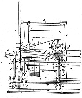
| Wilhelm, Parker & Hard - patent attorneysThis invention relates to wood working machines more particularly intended for shaping or forming the blades of boat oars. The machine is, however, adapted by proper adjustments thereof and the employment of suitable pattern guides, for the production of other articles of analogous shape. The blade of an oar ordinarily tapers or decreases in width from its outer end to its juncture with the loom or stem while it decreases in thickness from the loom to the wide outer or tip end. The machine forming the subject of this application is for giving this general shape to the blades, by successive cuts forming three flat faces or surfaces on each side of the blade. The central faces at opposite sides are parallel in a direction crosswise of the blade, while the other faces converge from the central faces toward the edges of the blade. After the blade is thus shaped it is finished by hand or by other suitable means. The carriage in the machine described is intended to be reciprocated by hand, but it could be reciprocated mechanically if desired.I claim as my invention:1. The combination of a driven cutter arranged in a relatively fixed location, a carriage arranged to reciprocate in a straight line past the cutter, devices on the carriage which hold the blank obliquely to the direction of movement of the carriage and which are rotatable to turn the blank about its axis, one of said holding devices embracing the blank between the ends thereof, a pattern past which the carriage moves, and a guide device which is connected to the blank holding means and is held against said pattern to regulate the turning of the blank as the carriage is advanced, substantially as set forth.2. The combination of a driven cutter arranged in a relatively fixed location, a carriage arranged to reciprocate in a plane parallel with the plane of the cutting edge of the cutter, devices on the carriage which hold the blank obliquely to the direction of movement of the carriage and which are rotatable to turn the blank axially and are adjustable to change the obliquity of the blank, one of no said holding devices embracing the blank between the ends thereof, a relatively stationary pattern, and a guide device which is connected to the blank-holding means and is held against said pattern as the carriage advances to regulate the turning of the blank, substantially as set forth.3. The combination of a saw arranged in a relatively fixed location, a carriage arranged to reciprocate in a plane parallel with the cutting plane of the saw, holding devices for the blank which are angularly adjustable on the carriage to regulate the obliquity of the blank to the direction of movement of the carriage and are freely rotatable to turn the blank about its axis, a pattern past which the carriage moves, an operating handle for the carriage secured to one of said holding devices, and a guide device which is connected to said holding device and is caused no to bear against said pattern as the carriage advances by hand pressure on said handle, substantially as set forth.4. The combination of a driven cutter, a carriage arranged to reciprocate past the cutter, means for holding the blank on the carriage and for turning the blank about its axis, two oppositely disposed patterns past which the carriage moves, and a guide device which is connected to the blank - holding means and is held against one of said patterns to regulate the turning of the blank in one direction and is held against the other pattern to regulate the turning of the blank in the opposite direction, substantially as set forth.5. The combination of a driven cutter, a carriage arranged to reciprocate past the cutter, means for holding the blank on the carriage and for turning the blank about its axis to present different portions thereof to the cutter, a pattern past which the carriage moves, and two devices projecting from said blank-holding means, each of which devices serves as a handle for holding the other against said pattern to guide the blank, one device acting as the guide in one position of the blank and the other acting as the guide in another position of the blank, substantially as set forth.6. The combination of a saw arranged in a relatively fixed location, a carriage arranged to reciprocate past the saw, blank holding devices on said carriage which are rotatable for turning the blank about its axis, one of said devices being adjustable laterally toward and from the plane of the saw and both of said devices being angularly adjustable to align them in different lateral adjustments of the first mentioned device whereby the blank can be held in different positions obliquely to the direction of movement of the carriage, a pattern plate past which the carriage moves, and a guide which is connected to one of said holding devices and is held against said pattern plate, substantially as set forth.7. The combination of a driven cutter, a carriage arranged to reciprocate past said cutter and also to swing toward and from the plane of the cutter, holding devices for the blank which are angularly adjustable, and one of which holding devices is also adjustable toward and from the plane of the cutter, said holding devices being also constructed to turn the blank about its axis, and guide means for said blank, substantially as set forth.8. The combination of a driven cutter, a carriage arranged to reciprocate past, the cutter and also to swing toward and from the plane of the cutter, holding devices for the blank which are angularly adjustable on the carriage and one of which is adjustable toward and from the plane of the cutter, said holding devices being also rotatable to turn the blank about its axis, a guide device secured to one of said holding devices, and a pattern plate against which said guide device bears as the carriage is advanced, substantially as set forth.9. The combination of a driven cutter, a carriage arranged to reciprocate past said cutter and having grooved supporting wheels, a track having a rounded face on which said carriage wheels travel whereby the carriage is adapted to swing toward and from the cutter, means for guiding said carriage, and means for guiding the blank in the advance movement of the carriage, substantially as set forth.10. The combination of a driven cutter, a carriage consisting of upright end posts, and horizontal bars adjustably connecting said end posts, supporting rollers for said carriage, a track on which said rollers travel, for adjusting the upper portion of one of said end posts toward and from the plane of said cutter, holding devices for the blank which are angularly adjustable on said carriage, and guide means for said carriage, substantially as set forth.11. The combination of a driven cutter arranged in a relatively fixed location, a carriage for holding the blank arranged to reciprocate lengthwise of the blank past said cutter, a holding device for the blade end of the blank, and a hollow chuck for holding the loom, clamping devices carried by said chuck and which are movable to grasp and release the loom, and means for turning said chuck, a pattern past which the carriage travels, and a guide secured to said chuck and bearing against said pattern to regulate the turning of said blank, substantially as set forth.12. The combination of a driven cutter arranged in a relatively fixed location, a carriage for holding the blank arranged to reciprocate lengthwise of the blank past said cutter, a holding device for the blade end of the blank, and a chuck for holding the loom comprising a rotatable open sided shell, clamping devices for the loom carried by said shell, and an open-sided support in which said shell is mounted to rotate, said holding device and said chuck support being angularly adjustable to hold the blank obliquely to the line of movement of the carriage, substantially as set forth.13. The combination of a saw arranged in relatively fixed location, a carriage arranged to reciprocate past the saw, means for rotatably holding the blank on the carriage, guide means for turning the blank as it passes the saw, a driven edge cutter, a pattern on the carriage, and means cooperating with said pattern to guide said edge cutter, substantially as set forth.14. The combination of a saw arranged in relatively fixed location, a carriage arranged to reciprocate past the saw, means for rotatably holding the blank on the carriage, guide means for turning the blank as it passes the saw, a movable driven edge cutter, a pattern on the carriage, means cooperating with said pattern to guide said edge cutter, and means for normally holding said edge cutter out of action, substantially as set forth. |
|