US Patent: 1,218,784
|
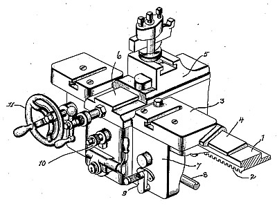
| Positive Apron Drive for Lathes
|
|
Patentees:
|
| Richard K. Le Blond (exact or similar names) - Cincinnati, OH |
| William F. Groene (exact or similar names) - Cincinnati, OH |
| Manufacturer: |
| Not known to have been produced |
|
|
Patent Dates:
|
| Applied: |
Oct. 14, 1915 |
| Granted: |
Mar. 13, 1917 |
|
Patent Pictures:
[
1 | 2
]
|
|
|
USPTO (New site tip)
Google Patents
Report data errors or omissions to steward
Joel Havens
"Vintage Machinery" entry for R. K. Leblond Machine Tool Co.
|
|
Description: |
| Robert P. Haines - patent attorney
In machines of this general character it has been proposed heretofore to provide an apron feed mechanism for imparting to the tool either its cross or lengthwise feed movements. Inasmuch as the feed movements of the carriage are liable to interruption from time to time or are to be adapted for different characters of work, it has heretofore been proposed to include in the apron feed mechanisms of such machines, a friction clutch and manually controlled means therefor, and such friction clutch has been found to be practically efficient in many kinds of work and it enables the carriage movements to be interrupted when desired and to be started again at the stopping point. A good practical form of such apron feed mechanism is shown in the prior patent granted to Le Blond and Groene, No. 980,971, January 10, 1911. Where an apron feed mechanism includes in its construction a friction clutch, there is a possibility at times and under certain conditions of work, that the clutch will slip and when the clutch members are disengaged, there is liability of the friction members creeping together or " winding up," as it is termed, and starting the feed. These actions of an apron feed provided with a friction clutch mechanism are well understood, and recognized in the art, but owing to the facility with which the carriage feed may be stopped and started at the same point, such friction clutch means are generally employed. In its broadest aspect, the present invention contemplates an apron feed provided with a driving member and a driven member and positive clutch connections, whereby said members may be placed in positive driving relation or disengaged from such position. In carrying this feature of the invention into practical effect, an apron feed mechanism of the general type of that shown and described in our prior Patent No. 980,971 is illustrated, wherein the tool may be given either cross or lengthwise feed movements, but it is to be understood, of course, that the invention is not restricted to this particular type of apron feed, and may be used effectively in other forms of apron feed mechanisms. In another aspect, an important feature of the present invention consists in forming the driving and driven members of the positive clutch of large diameters and providing them with a multiplicity of fine teeth to secure quick and satisfactory engagement. To this end, the gear deriving its motion from the feed rod of the lathe may be provided with a flange of large diameter having fine teeth extending therefrom, or such fine teeth may, of course, be secured to said gear and the driven member of the clutch may be provided in similar manner with a corresponding series of fine teeth. Motion from the driven member of the clutch may be transmitted to the feed elements in any suitable manner, and as a good form of means to this end, the driven member may have operatively connected to it, a gear from which a transmission train may be actuated. The present invention also provides means for positively effecting the engagement and disengagement of the driving and driven members of the apron feed to effect either cross or longitudinal feed movements. Such relative movements of the two clutch members to engage or disengage the fine teeth thereof may be variously effected, but a good practical form of the invention in this respect consists in manual means for moving the driven member to carry its large circle of fine teeth into engagement with the corresponding circle of fine teeth of the driving member. In the form of the invention illustrated, the driven member of the clutch is conveniently shown as formed on or connected to the hub of an elongated gear and clutch engaging and disengaging movements are effected in such illustrated form of the invention by movement of the elongated gear and driven member, but it will be understood that while this combination of elements is well adapted to the end desired, the essential in this respect is that the driven member having the large circle of fine teeth be movable into and out of engaging relation with the driving member and be operatively connected in any suitable manner with a gear for actuating the train of feed elements. To appropriately move the large circle of fine teeth of the two clutch members for quick and positive engagement or disengagement, manual means may be employed suitable to the purpose, but as shown in the illustrated form of the invention, such manual means consists of a rack and pinion arrangement, though obviously, this is not essential and may be variously modified. |
|

)
)