|
Description: |
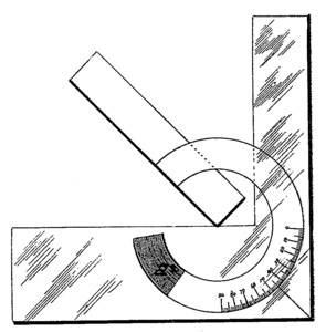
| Swasey's Bevel Protractor
The accompanying illustration represents a new instrument intended for the use of draughtsmen, machinists and surveyors. It was invented by Ambrose Swasey, at the shops of the Pratt & Whitney Co., of Hartford, Conn.
First, we have a plain steel square, one-eighth of an inch thick, the two sides of which are each five inches in length. A swinging rule, or blade A, is attached to the square by means of a circular piece B, which moves in a dovetailed slot, and may be set to move tight or loose by means of two screws and the binder C, depending upon the friction to hold it. The edge of the slot is marked with the different degrees, from zero up to 90°. In the illustration, each mark on the arc represents 5°, while in the regular instrument each of these degrees is marked. Both sides of the protractor presents a level face, so that it may lie flat upon the paper, and be used equally well on either side. The protractors in general use have a thumb-screw (to hold the blade), which projects from one side, in consequence of which only one side can be used.
The Swasey instrument is so arranged that any angle may be measured or drawn, whether acute or obtuse. Should the draughtsman wish to draw a line at an angle of 65° from his T square, set the zero mark on the sliding arc to that number, as indicated by the graduations, and placing the base of the square forming that angle with the swinging rule against the T square; then draw the desired angle. By simply turning the instrument one-quarter turn, round towards the right, so as to bring the other base of the square against the T square, will give an angle of 155°. If the instrument be now lifted by the right-hand corner and turned over towards the left (upside down), the angle formed will be 25°
Again, if the instrument be placed in the first position, as shown in drawing, the angle being 65°, taking hold of the left-hand corner and turning it over (upside down), will give an opposite angle of 115°. From the foregoing illustrations, the reader will understand that after drawing an angle of 60°, by turning the instrument over the same angle may be drawn but pointing in the opposite direction. The advantages of these problems may be readily understood by draughtsmen, as by simply turning the instrument, any angle, or its complement, may be drawn at once. This instrument is particularly adapted to the measurement of angles drawn upon paper or any other plane surface, as the swinging rule being the same thickness as the square, the edges of both lie even upon the paper, thus the protractor can be more accurately adjusted to the lines than if one edge were raised above the surface, as is the case with most protractors.
Another practical advantage in having both sides of the protractor even is, when the angles of solid bodies are to be measured, as in the case of crystals, pieces of machinery, etc., there is no difficulty in holding it firmly and squarely upon the piece to be measured, at the same time forming the angle between the swinging rule and body of the tool, open to the apex. The cross-section lines of complicated parts of machinery, where a number of angles are required to bring out the different parts distinctly, may be readily drawn by adjusting the swinging rule.
American Machinist, 24 Jan 1880, pg. 7 |
|

)
)