GB Patent: GB-190,605,511
|
| An Improved Mode of Arranging Worm Driving Gear
|
|
Patentees:
|
| Christopher William James (exact or similar names) - Hythe, Kent, England |
| Joseph Hartley Wicksteed (exact or similar names) - Leeds, England |
| Manufacturer: |
| Not known to have been produced |
|
|
Patent Dates:
|
| Applied: |
Mar. 07, 1906 |
| Granted: |
Jan. 10, 1907 |
Espacenet patent
Report data errors or omissions to steward
Joel Havens
Christopher William James
Joseph Hartley Wicksteed
"Vintage Machinery" entry for Joshua Buckton & Co.
|
|
Description: |
| Note: Early English patents (pre 1916) were numbered by the year and started at patent #1 at the start of each year in January. The patent # used in DATAMP represents the year of issue of the application and the patent #. This patent is #5511 of the year 1906.
Abstract:
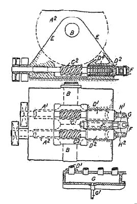
Relates to a method of arranging worm gearing. The driven shaft B, Figs. 1 and 2, has a number of worm-wheels A', A<2>, &c. which are driven by a corresponding number of worm shafts C<1>, C<2>, &c. The ends of the worm shafts are enclosed in thrust bearings D<1>, D<2>, the end thrusts being balanced by an arrangement of levers H', H', G. The lever G is pivoted at F and secured by a bolt f to the bed - plate. In the collar thrust bearing shown in Fig. 1, the half-bushes D<4> are nested in the sliding sleeve D<2>, which in turn is fitted in the bed-plate or headstock E of the driving- gear. Arrangements of levers are also deecribed for three or four worm shafts so that each worm similarly acts as the support or abutment of the other. In an alternative hydraulic compensating arrangement, the ends of the sleeves D<1> &c. project into a pressure box G, Fig. 5, kept full of oil or other liquid by means of a pump &c. through the pipe G'. The arrangements may be used with racks in lieu of worm-wheels, and they may be applied to planing-machines.
|
|