GB Patent: GB-191,511,790
|
| Improvements in Short-Circuiting and Brush Lifting Gear for Alternating Current Motors
|
|
Patentee:
|
|
| Henry Bertram Whitmore (exact or similar names) - Brereton Cottage, Cheshire County, England |
| Manufacturer: |
| Not known to have been produced |
|
|
Patent Dates:
|
| Applied: |
Aug. 16, 1915 |
| Granted: |
Aug. 10, 1916 |
|
Patent Pictures:
[
1 | 2
]
|
|
|
Espacenet patent
Report data errors or omissions to steward
Jeff Joslin
"Vintage Machinery" entry for Lancashire Dynamo & Motor Co., Ltd.
|
|
Description: |
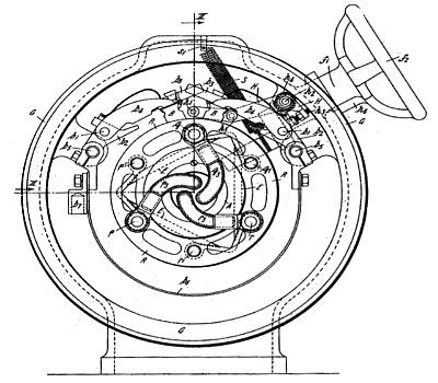
| Abstract:
Alternating - current induction machines; brush-holders; collecting-rings.- In slip - ring short - circuiting and brush-lifting gear for induction motors, each slip-ring P, Q, R is electrically connected to a pair of bars p p<1>, q q<1>, r r<1> which extend axially through the other two slip-rings but are insulated therefrom; each bar. may be made in two parts screwed into a slip-ring, as shown in connection with the bar q and slip-ring Q. The respective pairs of bars are connected together at one end by contact plates p<2>, q<2>, r<2>; at the other end, the three ends p<3>, q<3>, r' of the rotor windings are connected respectively to one bar of each pair. A rotating sleeve D carrying three tangentially-arranged shortcircuiting brushes E may be moved axially into contact with the plates p', q', r' to short-circuit the slip-rings, the edges of the plates being bevelled to allow the brushes to slide into position. The sleeve D is held in its end position by means of a spring- pressed ball d' engaging notches in the shaft. Axial movement is imparted to the sleeve by means of a crank-pin entering a groove therein and carried by a shaft f<1> fitted with a hand-wheel f<2>; the crank-pin is connected by a spring S to a projection s<1> on the casing tending to hold the crank in one or other of its extreme positions. Each slip-ring is fitted with a pair of brushes B carried from pins b<1> in brackets b<2>, and the extensions b<3> of the fingers b<4> overlap in elevation; the brackets b<2> are carried by, but insulated from, the brush-carrying bars b<5>, and the two brushes of each pair are connected together by a strip b<6> and are joined to a connecting-lug b<7>. The brushes are lifted off the slip-rings by the tall-pin h<5> carried by the lever H fulcrumed on the pivot h<2>; the lever H is fitted with an adjustable stop-pin h<3>, and a spring h<4> tends to keep the lever in position. The lever also carries a second tailpin h<1>, which extends underneath the extensions b<3> of the brush-fingers b<4>. In a modification, the contact plates p<2>, q<2>, r<2> are straight and are also tangentially arranged. The movement of the shaft f<1> may be effected automatically by means depending on the speed, voltage, current, or frequency. |
|

)
)