GB Patent: GB-294,594
|
| Improvements in Machines for Grinding Spherical Articles
|
|
Patentee:
|
|
| John Emery Caster (exact or similar names) - Cincinnati, Hamilton County, OH |
|
|
Patent Dates:
|
| Applied: |
Oct. 25, 1927 |
| Granted: |
Nov. 15, 1928 |
|
Patent Pictures:
[
1 | 2 | 3 | 4 | 5
]
|
|
|
Espacenet patent
Report data errors or omissions to steward
Joel Havens
"Vintage Machinery" entry for Cincinnati Grinders, Inc.
|
|
Description: |
| Abstract:
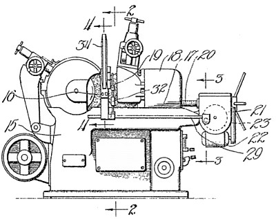
A centreless machine for grinding spherical articles, for example, balls for bearings, corsists of a grinding-wheel 16 having therein a series of annular grooves and a regulating-wheel 19, also grooved, the work being supported between the wheels on a rest 43, adjustable as to height by inclined surfaces on a member 44. The balls are fed automatically to the machine, and are moved from one groove to the next, or another, groove at intervals, the movement being timed to take place as the regulating-wheel is retracted from, and again advanced up to the grinding-wheel. These movements are brought about by a cam 23 which engages a toggle to move the slide carrying the regulating wheel, and also has a projection which, through rack gearing, oscillates a rock shaft 29, and this shaft, through linkage 32, 33, 36, Oscillates a shaft 63 journaled in a housing 34. In the housing, on sprockets 48, is mounted an endless chain 49 carrying grooved work feeding blades 50, which engage the halls and move them from groove to groove, the intermittent movement of the blades being effected by a pawl slidable in the housing and engaging rack teeth on the blades 50; the pawl is moved in one direction by a lever 61 on the shaft 63, and in the other direction, to move the work, by a spring. When the work 40 is to be moved into each groove, or every other groove, it is fed in a continuous stream down a tube 05, Fig. 10, into the grooves in the blades 50, oversize pieces being ejected automatically by engagement with a spring finger 68, which moves to allow the work to pass into a discharge passage. When the work pieces are to be advanced more than two grooves at a time, they are fed down three guide tubes, being released therefrom by the lifting of a detent, which is normally held down by a spring plunger, and is lifted by a notched disc mounted on the arm 33 and rotated intermittently by a pawl which engages a ratchet on the notched disc. |
|

)
)
)
)
)