US Patent: 305,963
|
| Micrometer Gage
|
|
Patentee:
|
|
| Frank H. Richards (exact or similar names) - Troy, NY |
| Manufacturer: |
| Not known to have been produced |
|
|
Patent Dates:
|
| Applied: |
May 19, 1884 |
| Granted: |
Sep. 30, 1884 |
USPTO (New site tip)
Google Patents
Report data errors or omissions to steward
Joel Havens
|
|
Description: |
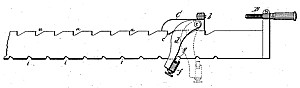
| My invention has relation to that class of implements employed for obtaining accurate measurements, using the micrometer screw for minute adjustments, and ordinarily known as "micrometer gages." The object of my invention is to produce a simple, cheap, and easily operating instrument of the class named, wherein the longer adjustments may be rapidly and accurately made, which shall be easy of construction, not liable to get out of order, and afford means of applying the principles of the micrometer caliper to the accurate measurement of greater dimensions than in former constructions. To accomplish this my improvements involve certain novel and useful peculiarities of construction, relative arrangements or combinations of parts, and principles of operation, all of which will be herein first fully described, and then pointed out in the claims. In the drawings, Figure 1 is a side elevation showing the construction and arrangement of my improved implement. Fig. 2 is a similar view showing the notches in the bar arranged so that their plain bearing-faces are reversed from the position indicated in Fig. 1. Fig. 3 is a side elevation showing a rod to be measured supported upon the bar of the implement. Fig. 4 represents a side and edge view of one of the supports detached from the bar. Fig. 5 is a sectional elevation showing the side plates, which are hinged upon the movable block, the hinge-pin, and the spring bolt and socket. In all these figures like letters of reference, wherever they occur, indicate corresponding parts A is the main bar of the implement, made, preferably, of metal,- and of any length desired, which length will determine the capacity of the instrument. |
|