US Patent: 335,781
|
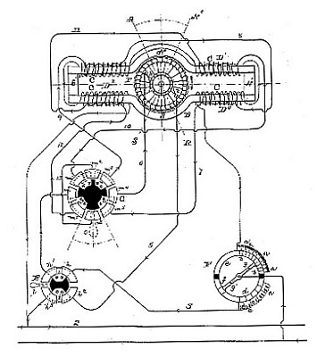
| Electric Dynamic Motor
|
|
Patentee:
|
|
| Frank J. Sprague (exact or similar names) - New York, NY |
| Manufacturer: |
| Not known to have been produced |
|
|
Patent Dates:
|
| Applied: |
Sep. 20, 1885 |
| Granted: |
Feb. 09, 1886 |
USPTO (New site tip)
Google Patents
Report data errors or omissions to steward
Joel Havens
Vintage Machinery entry for Sprague Electric Railway & Motor Co.
|
|
Description: |
| Abstract:
In the use of electro-dynamic motors difficulty has heretofore arisen from the necessity of shifting the commutator-brushes when the armature current is varied or reversed. The object of the present invention is mainly to obviate this difficulty, though the invention relates further to certain means of regulation employed in conjunction with the main features of the invention.
My invention is especially applicable for use with railway-motors, and motors for working elevators, and other motors
in parallel circuit in the operation of which it is necessary to vary the speed and to reverse the direction of rotation of the armature,and sometimes, also, to change the motor into a generator and to regulate it while in this condition, as set forth in my Patent No. 318,668, dated May 26, 1885.
As is well known, the reversal of direction of rotation of the armature of a motor or generator causes the reversal of the direction of lead of the brushes, and this lead is proportional to the armature current, and is also dependent inversely to the strength of the free field. In motors heretofore built for railroad work, it has been customary to provide two sets of commutator-brushes, one adapted to be used when the motor runs in one direction and the other for the opposite direction of rotation. These are set for different leads, and means are usually provided for changing the lead of each set. A single set of tangential brushes could not be employed because of the changes of lead and the sparking and burning which must attend such changes. Automatically operating devices have been proposed for changing the lead, but these are complicated contrivances, and are therefore not well adapted for railway purposes, where only the simplest apparatus should be employed.
In my Patent No. 324,891 is set forth a mode of winding for a motor, by which the non sparking points are maintained constant under varying armature-current. In this arrangement there is a set of series field-coils and a set of shunt field-coils, part of the series coils being wound on two diagonally-opposite legs of the field magnet in a manner to act cumulatively with the main or shunt field-coils, and the rest wound on the other two legs in a manner to differentiate the shunt coils, the differential being stronger than the cumulative series coils. This method is only for a machine running always in the same direction and at a determined speed on a constant potential circuit, and keeps the non-sparking point at a fixed position by opposing the distortion caused by the armature-current by a counter-distortion set up by the governing or series coil. While, if the current in the armature, and consequently the direction of rotation, is reversed, the distortion and counter distortion are also reversed, yet because of the uneven magnetizing effect of the two series while, if the current in the armacoils the amount of distortion is not the same as when running in the normal direction. This arrangement also therefore cannot be used for the purposes above set forth. By my present invention, however, I construct a machine with such a system of winding that it may run in either direction on a circuit of constant or of varying potential with a single or double set of tangential or end contact-brushes, with no change of lead, and consequently no necessity for changing the position of the brushes. By it the position of the brushes having been once properly adjusted is made independent of the amount of work the machine is doing, or the speed at which it is running, or whether it is acting as a motor or as a generator. It is independent also of the strength of field or armature current, and hence of the speed and power developed. I further provide means for varying strength of field and armature current either independently or simultaneously.
Claim:
An electrodynamic motor having a field magnet whose main poles are formed by cores extending in opposite directions, having a set of shunt-coils wound evenly on all said cores, and a set of series coils, also wound evenly thereon, said sets being arranged to form polar lines at right angles to each other. |
|