GB Patent: GB-345,690
|
| Improved Feed Mechanism For Drilling, Boring, Facing And Other Machines
|
|
Patentees:
|
| George Adcock (exact or similar names) - Leicester, England |
| Howard Shipley (exact or similar names) - Leicester, England |
|
|
Patent Dates:
|
| Applied: |
Jan. 03, 1930 |
| Granted: |
Apr. 02, 1931 |
Espacenet patent
Report data errors or omissions to steward
Joel Havens
"Vintage Machinery" entry for Adcock & Shipley Ltd.
|
|
Description: |
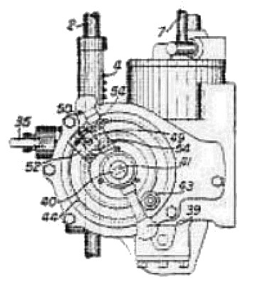
| In a feed mechanism for a boring, drilling, facing, or similar machine a carrier for one or more adjustable dogs is rotatable or reciprocable together with the spindle feed-shaft and acts through the dogs, levers, &c. to cause clutches to be actuated to vary the speed of the feed by means of an overrunning free-wheel clutch. The drill may be advanced rapidly to the work, then be given a slow cutting feed and next be rapidly retracted or advanced rapidly to a second portion of the work for a further cutting operation. The drill-spindle 2 is fed by the usual quill 4 meshing with a pinion 5, Fig. 2, secured to a shaft 6. A vertical shaft 7 driven from the drill-spindle rotates, through gearing 8, a worm spindle 9 engaging a worm-wheel 10 rotatable on the shaft 6 and through further gearing a shaft 13 connected by bevel gears 14 and spur gears 16, 17 to the rotatable carrier 18 secured to the shaft 6. A roller ratchet 12 connects the worm-wheel 10 to a sleeve 11 which may be clutched to the shaft 6 after the manner described in Specification 287,304, [Class 83 (iii), Metals, cutting], by means of a clutch 23 keyed to the shaft and slidable axially by a spring-opposed plunger 42, a ball 41 and a circumferential groove 40 in a hand lever 39 slidable transversely through the shaft. In operation the feed is started by raising a hand lever 35 so as to rock a shaft 34 and cause a cam 36 thereon to oscillate a lever 37 and displace the handle 39 transversely to the shaft 6, thereby engaging the clutch 11, 23 and enabling the shaft 6 to be rotated slowly by the worm-wheel 10. Simultaneously a pinion 33, Fig. 1, on the end of the shaft 34 engages rack teeth on a stop 31 to withdraw the stop from under the end 30 of a lever 29 secured to a shaft 24. A spring plunger 47 then rocks the shaft 24 and causes a yoke thereon to actuate a clutch connecting the shaft 15 with the shaft 13, thus enabling the shaft 6 to be rotated rapidly through the gearing 16, 18 whilst the ratchet 12 is overrun. A lever 27 secured to the shaft 24 carries a pin 28 which, when the shaft is rocked by the spring 47, lies in the path of a dog 20 adjustably secured in a circular groove 19 of the carrier 18 so that at a predetermined point the shaft 24 will be rocked in the reverse direction and will disconnect the rapid drive to the shaft 6. The worm-wheel 12 then applies a slow cutting feed to the drill, which continues until an adjustable stationary stop 43 engages a cam 45 on the handle 39 to disconnect the clutch 11, 23 and allow the drill to be retracted by a spring 46 or a weight. As soon as the lever 35 is released by the operator, a spring (not shown) tends to return the stop 31 to operative position so that immediately the lever 27 is rocked by the dog 20 the stop may shoot under the lever 29 and prevent the rapid feed from being engaged until the cutting operation has been completed. This is further prevented by the pin 28 riding on the outer edge of the dog 20. In a modification the clutch for the rapid feed is first engaged by the hand lever 35, Fig. 7, whereupon the shaft 6 is rotated rapidly to feed the drill to the work. A cone 54 on the handle 39 then contacts with a pivoted catch 49 backed by a stop 52 adjustably secured in a circular groove 44 of the machine frame, causing the handle to engage the slow feed clutch 23 which is overrun until the rapid clutch is disengaged by the dog on the carrier 18. The slow feed acts alone until the fixed stop 43 engages a second cone 54 on the handle 39 to disconnect the clutch 23 and allow the spindle to be returned. On the reverse rotation of the shaft 6 the handle 39 rotates the catch 49 about its pivot 50 and passes it without engaging the clutch 23. In a further modification in which several cutting feeds in the same direction are alternated with rapid traverses, the carrier 18, Fig. 11, is provided with a number of dogs 55, 56, between each pair of which a cam 57 is mounted. While the rapid feed is overrunning the ratchet clutch a dog 55 engages the pin 28 as described above to disconnect the rapid feed, the cutting feed then continuing until the cam 57 acts on the end of the stop 31 to allow the shaft 24 to be rotated by the spring plunger 47 and re-engage the rapid clutch. The carrier 18, instead of being rotated by the drill-spindle, may be reciprocated and carry the dogs 20 in a straight slot. |
|