|
Description: |
| Church & Church - patent attorneys
William Lodge was a partner in Lodge & Davis Machine Tool Co. of Cincinnati, OH, which was a predecessor of the American Tool Works. He went on to found the Lodge & Shipley Machine Tool Co.
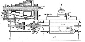
This invention relates to improvements in lathes such for instance, as shown and described in Patent No. 468,183, dated February 2, 1892, to which reference is made, and it has for its object to simplify and improve the mechanism of such lathes whereby they may be more easily and quickly adjusted and adapted for use in turning a greater variety of work.
Having thus described my invention, what I claim as new is;
1. In an engine lathe, the combination with the spindle and feed screw, and the counter shaft from which the feed screw is driven, of the segment pivoted on said counter shaft, the gear wheel on the counter shaft, the gear wheels on the spindle and the idler gears carried by the segment movable longitudinally on their centers and meshing with either of the gear wheels on the spindle and with the gear on the counter shaft; substantially as described.
2. In an engine lathe, the combination with the spindle and gear wheel thereon, of the adjustable segment having the smooth stud, the gear wheels movably mounted on said stud and having the flanges embracing the gear wheel on the spindle when the same are in mesh and the feed screw driven from the gears on the segment; substantially as described.
3. In an engine lathe, the combination with the spindle having the different sized gear wheels thereon, the countershaft from which, the feed screw is driven and the gear wheel on said counter shaft, of the adjustable segment pivoted on the counter shaft, the different sized gear wheels-journaled on said segment and bodily movable thereon to mesh with either of the gear wheels on the spindle and the idler gear completing the train of gears between the spindle and counter shaft; substantially as described.
4. In an engine lathe, the combination with the spindle and feed screw, of the different sized gear wheels rigidly mounted on the spindle and separated a distance equal to the thickness of one gear wheel and the movable gearwheels of different size rigidly connected together and adapted to mesh with one or the other of the gear wheels on the spindle, the one of said movable gear wheels not in mesh occupying the space between the gear wheels on the. spindle, the feed screw being driven from said movable gear wheels; substantially as described.
5. In an engine lathe, the combination with the spindle, the feed screw, and a cone of gear 95 wheels from which said feed screw is driven, a bell-crank tumbler movable longitudinally of the cone, a gear wheel and idler gear wheel carried by the tumbler and means for varying the speed transmitted to the gearing on too the tumbler, of an extension of said tumbler protruding from the head stock and provided with means for retaining it in the desired position relative to a gage plate.
6. In an engine lathe, the combination with the spindle; the feed screw and a cone of gear wheels from which said screw is driven, a bell-crank tumbler movable longitudinally of the cone, gear wheel and idler gear wheel carried by the tumbler, included within the head-stock; and means for varying the speed transmitted to the gearing on the tumbler, of an extension of said tumbler protruding from the head stock and provided with a pin for retaining it in the desired position relative to a gage plate.
7. In an engine lathe, the combination with the spindle, feed screw driven therefrom and reversing mechanism interposed between said feed screw and spindle, the clutch controlling said reversing mechanism, the clutch operating shaft, the carriage and upper slide thereon, the clutch slide carried by said upper slide and connections between said clutch slide and clutch operating shaft whereby by the transverse movement of the upper slide said clutch is operated as set forth.
8. In an engine lathe, the combination with the feed screw, reversing mechanism therefor, carriage and upper slide thereon having a groove or way therein, of the clutch operating shaft controlling the reversing mechanism, the block mounted on said, shaft, the clutch slide mounted in the way or groove in the upper slide, the bolt for clamping said clutch slide in position and connections between said clutch slide and block; substantially as described.
9. In an engine lathe, the combination with the feed screw, reversing mechanism therefor, carriage, upper slide and clutch operating shaft controlling the reversing mechanism, of the block on said clutch operating shaft, the clutch slide carried by the upper slide, the link connected to said clutch slide and the adjustable clip connecting said link and block whereby the direction of movement of the clutch operating shaft with relation to the movement of the upper slide may be changed; substantially as described.
10. In an engine lathe, the combination with the feed screw, carriage, upper slide thereon and clutch operating shaft controlling the reversing mechanism, of the block mounted on said clutch operating shaft and having the portions projecting on each side of said shaft; the clutch slide carried by the upper slide and the link and adjustable clip connecting said slide and block; substantially as described.
11. In an engine lathe, the combination with the feed screw, carriage, reversing mechanism for the feed screw and clutch operating shaft controlling the reversing mechanism, of the block mounted on said shaft the clutch slide connected to said block and moving longitudinally with the carriage, the operating handle for said clutch slide and the link connecting the slide and handle; substantially as described.
12. In an engine lathe, the combination with the bed, carriage, apron gearing thereon having a cone of gear wheels and apron feed shaft, of the gear wheel rotating with said shaft, the carrier and an idler wheel journaled thereon, meshing with the gear wheel on the shaft and adapted to mesh with any one of the gears in the cone; substantially as described.
13. In an engine lathe, the combination with the bed, carriage, apron gearing thereon having a cone of gear wheels and the apron feed shaft, of the gear wheel on said shaft, the carrier moving with the carriage and pivoted on the shaft and the idler wheel on said carrier meshing with the gear wheel on the shaft and adapted to mesh with any one of the gear wheels in the cone; substantially as described.
14. In an engine lathe, the combination with the bed, carriage, apron gearing thereon having a cone of gear wheels and the apron feed shaft, of the gear wheel on said shaft, the carrier pivoted on the shaft and embracing the gear wheel, the idler wheel on the carrier meshing with said last mentioned gear wheel and adapted to mesh with any one of the gear wheels forming the cone and the arm on the carrier cooperating with a gage plate on the apron to indicate the position of the gears; substantially as described.
15. In an engine lathe, the combination with the bed, carriage, apron gearing carried thereby and embodying a cone of gear wheels and the apron feed shaft, of the gear wheel on the apron feed shaft, the carrier pivoted on said shaft and having the idler wheel meshing with said gear wheel and adapted to mesh with any one of the gears in the cone, the handle on the carrier, a locking catch on the handle and a gage plate on the carriage with which said catch cooperates; substantially as described.
16. In an engine lathe, the combination with the bed, longitudinally movable carriage and transversely movable slide mounted on said carriage and having the rearward projection, and the screw for moving said slide detachably engaged therewith, of the supplemental carriage, a clamp for holding it in adjusted position, the adjustable guide on said supplemental carriage and the slide block detachably connected with the transversely movable slide and working in the adjustable guide; substantially as described.
17. In an engine lathe, the combination with the bed, longitudinally movable carriage and transversely movable slide mounted on said carriage and having the slotted rearward projection, the screw for moving the slide and the nut connecting the slide and screw secured in the slot of the rearward extension, of the supplemental carriage, a clamp for holding it in adjusted position, the adjustable guide on said supplemental carriage and the slide block adjustably connected with the rearward extension of the slide and working in the adjustable guide; substantially as described.
|
|