|
Description: |
| Abstract:
The present invention relates to a circuit-breaker, and is embodied in a circuit-breaker especially adapted for use as an igniting device for explosion-engines.
In accordance with the invention the separable terminals which produce the spark are normally yieldingly held in contact with each other as by a weight or spring and are provided with an actuating device for separating the same in order to produce a spark. The said actuating device is arranged to first separate the terminals and in its continued movement to control the restoration thereof, so that it is practicable to separate and restore the terminals at any rate of movement thereof which may be desired.
In circuit-breakers which are intended for the production of a spark it is desirable that the terminals should be separated to a considerable extent with a rapid and sudden movement to produce the spark, it being further desirable, however, that they should be restored with a gradual movement in order not to come together with a shock, which in the operation of a gas-engine, for example, soon Wears out the terminals, so that they have to be renewed. These ends can be accomplished in accordance with the present invention by so arranging the terminals with relation to the actuating device that they are separated to the maximum extent during a comparatively-short part of the movement of the actuating device and are restored as gradually as may be desired under the subsequent control of the actuating device in accordance with the invention.
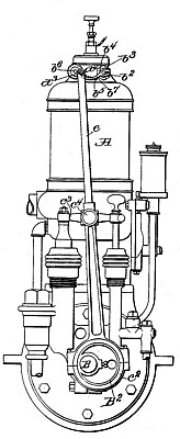
The invention is herein shown as applied to a gas-engine, which forms the subject of another application filed by me June l, 1897, Serial No. 638,941 (patent #713,792), and while igniting devices embodying the essential features of the n present invention may obviously be used with any explosion-engine the invention will be described as applied to the particular engine aforesaid. In this engine the actuating device for the igniter is arranged to travel, as will be hereinafter described, in a curved path, and to adapt the igniter to the peculiar movement of the actuator the movable terminal thereof is herein shown as mounted on a rock-shaft extending through a wall of the explosion-chamber, the said rock-shaft having a lever-arm extending into or across the path of travel of the said actuator. The said lever-arm is provided with a shoulder which is near the rock-shaft, upon which the lever is mounted and which is substantially transverse to the path of the actuating device aforesaid. As the said actuating device passes the rock-shaft, therefore, it will engage the said shoulder substantially at a right angle thereto and rock the shaft upon which the lever and terminal are mounted until the edge of the shoulder, which travels on an arc, meets the path of the actuator, the rapidity of movement of the terminal depending upon the distance of the part of the shoulder which is first engaged from the axis on which the terminal moves. The said lever-arm is further provided With a supplemental engaging surface beyond the shoulder, along which the actuating device travels, the terminal being provided with restoring means, such as a spring, 'but being controlled in its movement in response thereto by the engagement of the supplemental engaging surface with the actuator, the said supplemental surface being so shaped with relation to the path of movement of the actuator that the terminal will come in contact with its mate before said surface is left by the actuator, thus insuring a comparatively slow and gradual movement.
Claims:
l. A circuit-breaker comprising a fixed terminal, a movable terminal provided with an engaging portion; means for yieldingly holding said movable terminal in contact with the fixed terminal; and a traveling actuator adapted to engage said engaging portion and by its first engagement to quickly separate the terminals, the path of said actuator being such that the actuator remains in engagement and controls the return movement of said movable terminal so as to permit the gradual restoration thereof, the terminal being substantially wholly restored before the actuator is out of engagement.
2. A circuit-breaker comprising a fixed terminal, a movable terminal consisting of a finger projecting radially from a rock-shaft, means for yieldingly holding said movable terminal in contact with the fixed terminal, an arm or projection connected with said rock-shaft, and a traveling actuator arranged to initially engage said arm at a point near said rock-shaft and to travel along in engagement with said arm, the path of movement of said actuator being such as to permit the gradual restoration of said arm to its normal position, as set forth.
3. The herein-described circuit-breaker or igniting device which comprises a fixed terminal, a movable terminal, an actuator for said movable terminal, an engaging portion of said movable terminal projecting across the path of said actuator, and a supplemental engaging portion, the surface of said engaging portion and the path of said actuating device approaching each other in the direction of movement of the latter, substantially as described.
4. The herein described circuit breaker which comprises a stationary electric terminal, a movable terminal normally in contact therewith, an actuator for said movable terminal, an engaging portion of said movable terminal in the path of said actuator, and a supplemental engaging portion adjacent to the main engaging portion and adapted to be engaged by said actuator in the return movement of the movable terminal until said movable terminal is substantially restored to contact with said stationary terminal, substantially as described.
5. An igniting device for gas-engines comprising a stationary electric terminal within the cylinder or explosion-chamber of the engine, a movable terminal normally in contact therewith, an actuator for said movable terminal, and engaging portion of said movable terminal in the path of the said actuator, an engaged by said actuator in the return movement of the movable terminal until said movable terminal is substantially restored to contact with said stationary terminal, operating means for producing a continuous movement of said actuator, and a device for shifting the position of said actuator with relation to such operating means, substantially as described.
6. In an igniting device for gas-engines, the combination with a stationary terminal within the cylinder or explosion-chamber of the engine, of a movable terminal normally in contact therewith but adapted to be moved therefrom to break the circuit and cause a spark, a rock-shaft or pivotal support for said movable terminal, an arm secured to said rock-shaft, an engaging device for said arm adapted to be moved along a curved path, a shoulder on said arm extending into said path, and an extension of said arm beyond said shoulder curved to substantially conform to the path in which the engaging projection travels, substantially as and for the purpose described.
7. In an igniting device for a gas-engine, the combination with a stationary terminal within the cylinder of the engine, of a movable terminal comprising a pivotally-supported arm adapted to be swung on its pivot to and from said stationary terminal, an operating arm connected to and pivoted coaxially with said terminal arm, a lever provided at one end with an eccentric-strap adapted to cooperate with an eccentric on the main shaft of the engine, a projection at the other end of said lever adapted during the movement thereof to engage said operating-arm for the igniting device, a guide pivotally connected to said lever and adapted to move in a rectilinear direction whereby the end of said lever which carries the engaging portion is caused to move in a curved path, a shoulder on the arm which operates the igniting device near the pivotal axis thereof and in the path of the said projection, and a curved portion of said arm beyond said shoulder, substantially as and for the purpose described.
8. In an igniting device for gas-engines, the combination with a circuit-breaker having a fixed terminal within the cylinder of the engine, of a movable terminal mounted on a rock-shaft in a Wall of said cylinder, an arm secured to said rock-shaft outside of the said cylinder, a lever provided at one end with an eccentric adapted to cooperate with an eccentric on the main shaft of the engine, an engaging device at the opposite end of said lever adapted to engage said arm, a guide or cross-head for said lever whereby the said engaging projection is adapted to travel on a curved path, a shoulder on said arm extending into the path of travel of said projection and adapted to be engaged thereby to rock the said rock-shaft to separate the electric terminals, a curved engaging portion on said arm beyond the said shoulder in the path of travel of said projection to permit the gradual return movement thereof, a restoring spring for said arm, and means for shifting the position of the engaging projection with relation to said lever, substantially as the purpose described.
|
|