|
Description: |
| Abstract:
My invention relates to certain improvements in gas-engines of the type shown in the Letters Patent of the United States granted to me January 5, 1897, No. 574,610.
In my prior patent I employed a cam upon the shaft of the engine which by means of certain connections operated the exhaust-valve every second rotation, as is necessary in this type of engines; but the connections therein employed necessitated the use spring-pressure to hold the two members of the exhaust-valve rod in operative engagement, which was objectionable, as they should be held positively together during their time of operation to prevent any possible disengagement. In my improved construction, I employ an eccentric upon the-shaft instead of the objectionable cam and also radically different connections between the eccentric and the exhaust-valve, which serve to lock the two members of the exhaust-valve rod positively together instead of depending upon spring-pressure to preserve their connection. Moreover, in my prior patent, I employed an exhaust-chamber whose connection with the cylinder was controlled entirely by the exhaust-valve, While in my present construction, I employ an exhaust-aperture opening directly from the cylinder into the atmosphere and cooperating with the piston to permit of the discharge of the compressed products of combustion at the end of the operative stroke of the cylinder, thus leaving only the contents of the cylinder at atmospheric pressure to be discharged through the exhaust-valve when the piston returns to its initial position preparatory to the second forward stroke, which serves to draw-in the supply of fresh air and gas. This novel construction serves to reduce materially the resistance to be overcome, in the operation of the engine and is a valuable feature.
Another improvement over the structure of my prior patent consists in the employment of a novel fuel-feed operating by the action of gravity from the reservoir instead of being positively pumped therefrom, as in my aforesaid prior patent.
My invention is also concerned with a novel speed-governing mechanism in which any undue increase in the speed of the engine serves to wholly or partially shut 0E the supply of oil instead of preventing its entry to the ignition-chamber, as in my prior patent, thus preventing the waste of oil which would necessarily follow in my prior construction when the speed-governing mechanism came into action. Connected also with this feature of my invention is the novel mechanism for determining at what increase of speed the governing mechanism shall be brought into action to slow the engine down.
Another feature of my speed governing mechanism is embodied in a construction in which as the supply of oil or gas is decreased the amount of air admitted to the cylinder is also proportionately diminished, so that the proportion of air and gas will always remain constant and at the highest point of efficiency for explosive purposes.
Claims:
l. In a device of the class described, the combination of an oil-reservoir adjacent the air-inlet pipe, with means for keeping the oil in said reservoir at a constant height, a small pipe opening into said reservoir at or slightly below the level at which the oil stands and leading downward at a slight angle to the horizontal and opening into the air-inlet pipe, a governor controlled by the speed of the engine, and a sleeve in said reservoir adapted to be moved by the governor to control the supply of oil admitted to the air-inlet pipe.
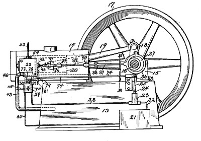
2. In a device of the class described, the combination with the ignition chamber having the lug 32 projecting from the bottom thereof, of the yoke 30 secured to said lug, and the reservoir 29 secured to the-bottom of said yoke, substantially as and for the purpose described.
3. In a device of the class described, the combination of the ignition-chamber having the lug 32 projecting there-from, the yoke 30 secured to said lug, the reservoir 29 secured to said yoke, the sleeve 58 in the top of said reservoir, and the valve 55 having its stem 56 extending through the lug 32 and the sleeve 58.
4. In a device of the class described, the combination of the ignition-chamber having the lug 32 projecting therefrom, the yoke 30 secured to said lug, the reservoir 29 secured to said yoke, the sleeve 58 in the top of said reservoir, the valve 55 having its stem 56 extending through the lug 32 and the sleeve 58,
5. In a device-of the class described, the v combination of the feed-pipe for supplying fuel to the engine, the reservoir into which said pipe opens provided with the cylinder 36 having an aperture therein leading to said pipe, the sleeve 58 sliding in said cylinder and adapted to close said aperture, a spring 6l tending to hold the sleeve above the aperture, the rock-shaft 74, the spring 79 adapted to hold the shaft in its inoperative position, the arm 77 extending from the shaft to the sleeve 58, and a governor operatively connected to said shaft to rock it when a certain speed is attained.
6. In a device of the class described, the combination of the cylinder, an air-suction pipe connected therewith into which the vaporizing fluid is admitted, with a feed device for supplying the vaporizing fluid to said air-suction pipe, governing mechanism controlled by the speed of the engine, and connections between said governing device and the feed device for simultaneously limiting the quantity of vaporizing fluid admitted to the air-suction pipe, and the amount of air admitted to the cylinder, said connections comprising a closure for the vaporizing-fluid device, the valve governing the admission of air to the cylinder, and a spring controlling said valve and closure, and put under tension by the operation of either.
7. In a device of the class described, the combination of the cylinder, a valve controlling the admission of air charged with gas thereto, with a feed device for the vaporizing fluid, means for limiting the operation of said feed device, and connections between said valve and the feed device for simultaneously increasing the tension on said valve and limiting the operation of said feed device.
8. In a device of the class described, the combination of the cylinder, a valve controlling the admission of air charged with gas thereto, with a feed device for the vaporizing fluid, means for limiting the operation of said feed device, and connections between said valve and the feed device for simultaneously increasing the tension on said valve and limiting the operation of said feed device, said connections comprising a spring interposed between said valve and said feed device and put under tension by the operation of either mechanism.
9. In a device of the class described, the combination of the ignition-chamber, the exhaust-valve 55 located therein and having the stem 56 extending therefrom, the reservoir 29 supported beneath said valve and containing the cylinder 86, the supply-pipe opening into the said cylinder, the sleeve 58 mounted in said cylinder and normally extending above the opening for the supply pipe, and having the stem 59 extending , and a spring 6l interposed between the end of said stem and said sleeve 5S, substantially as and for the purpose described.
10. In a device of the class described, the combination of the feed-pipe for supplying fuel to the engine, with a closure for the same, a governor controlling said closure, a coiled spring normally resisting the movement of said closure, and graduated means for increasing the tension of the spring to any desired amount consisting of the notched piece 81 with which the extended end 79 of the coiled spring is adapted to cooperate, substantially as and for the purpose described.
11. In a device of the class described, the combination of the cylinder, an air-suction pipe connected therewith into which the vaporizing fluid is admitted, with a feed device for supplying the vaporizing fluid to said air-suction pipe, governing mechanism controlled by the speed of the engine, and connections between said governing device and the feed device for simultaneously limiting the quantity of vaporizing fluid admitted to the air suction pipe, and the amount of air admitted to the cylinder, said connections comprising a closure for the vaporizing-fluid device, the valve governing the admission of air to the cylinder, and yielding connections between the valve and the closure whereby the closure may be operated to absolutely shut off the vaporizing fluid while the valve is not closed against high pressure.
|
|