US Patent: 2,068,529
|
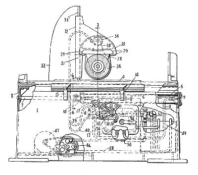
| Grinding Machine
|
|
Patentee:
|
|
| William G. Baldenhofer (exact or similar names) - Springfield, Clark County, OH |
|
|
Patent Dates:
|
| Applied: |
Mar. 28, 1932 |
| Granted: |
Jan. 19, 1937 |
USPTO (New site tip)
Google Patents
Report data errors or omissions to steward
Joel Havens
Vintage Machinery entry for Brown & Sharpe Mfg. Co.
Vintage Machinery entry for Thompson Grinder Co.
|
|
Description: |
| This patent was listed on a Thompson Grinder Co. patent plate, and also on a Brown & Sharpe patent plate.
Abstract:
This invention relates to improvements in grinding machines of the class known as surface grinding machines, and more particularly to that class in which the work-holder and tool-holder are reciprocally operated by fluid motors, the fluid preferably being a mineral oil under pressure. In machines of this class the work-holder is reciprocated by means of a fluid motor consisting of a cylinder, piston and piston rod. The toolhead is usually advanced or retracted in successive intermittent movements of varying extent by a similar motor, the intermittent movements being timed to occur at the ends of the working strokes of the work-holder. The grinding operation is performed on the work supported on the work-holder by peripheral contact of a rotatable grinding wheel, which is mounted on the outer end of a wheel spindle supported in a horizontally disposed toolhead in such manner that the longitudinal axis of the spindle is located at right-angles to the direction of travel of the work- holder, whereby a flat surface is produced on the work by feeding the wheel across the work in successively intermittent movements. The machine described in the present specification follows a customary practice in providing reversing mechanism which is operated by stop- dogs adjustably secured to the work-holder, this mechanism governing the reversals of the work- holder, and also by the provision whereby the fluid under pressure is supplied to the separate fluid motors from a common source. In the present machine the intermittent feed imparted to the toolholder is obtained by supplying successive predetermined quantities of fluid to the same end of the cylinder of the toolholder motor, and both the toolholder motor and the work-holder motor are supplied from the same source of fluid under pressure. One of the disadvantages of such an arrangement has been that due to varying fluid pressures when the speed of the work-holder is changed, successive charges of fluid of a different quantity will be 1admitted to the toolholder motor resulting in a change in the extent of the intermittent feeds of the toolholder. If the speed of the work-holder motor is decreased, the successive intermittent movements of the toolholder become greater, and 5if the speed of the work-holder motor is increased the extent of the successive feeds of the toolholder is reduced. As a consequence of this, unless provision is made otherwise for preventing it, the quantity of the successive fluid charges admitted to the toolholder motor will obviously vary at different speeds of the work-holder resulting in a variation in the feed of the toolholder. One of the objects of this invention is to overcome this objection by providing that uniform successive charges of fluid will be admitted to the toolholder motor regardless of the speed of the work-holder. Another object of the invention is the provision of means incorporated in a unitary hydraulic valve control mechanism, whereby a smoothly operating machine is afforded. One of the advantages of fluid motor drive is that infinite gradation of work-holder speeds is readily obtainable. Ordinarily, however, the operation is hampered by vibration due to shock at work-holder reversals. The present invention provides a cushioning effect whereby all shock is eliminated. Another object is the provision of improved means for controlling the extent of each intermittent movement of the tool-head, which means may also be employed to alter the direction of movement of the toolholder. Another object is to provide means acting in combination with the devices just mentioned which control the toolhead movements whereby a continuous movement may be given the toolhead in either direction, the direction being under the control of the intermittent control means. Another object is to provide that the toolhead is maintained in position during the intervals between times of movement; that is, the toolhead is substantially in a "locked" position.
Claim:
In a machine of the character described, a plurality of fluid motors operating from the same source of fluid supply, manual means for regulating the fluid supplied to one of said motors, and fluid admission means operated directly by fluid for admitting successive predetermined charges of the fluid to another of said motors also operable from the same source of fluid supply. |
|