GB Patent: GB-491,152
|
| Improvements in or Relating to Milling Machine-Tools
|
|
Patentee:
|
|
| none listed (exact or similar names) - Providence, Providence County, RI |
|
|
Patent Dates:
|
| Applied: |
May 07, 1936 |
| Granted: |
Aug. 26, 1938 |
Espacenet patent
Report data errors or omissions to steward
Joel Havens
Vintage Machinery entry for Brown & Sharpe Mfg. Co.
|
|
Description: |
| Abstract:
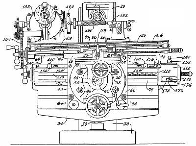
A milling-machine has a work-supporting table, a longitudinally movable support therefor, and driving connections for controlling the rate and direction of movement of the table and support comprising a prime mover, a transmission train for moving the table relatively to the support, another transmission train for moving the support, and separate control devices for each train to give starting, stopping and reverse, and a single control element which enables the table transmission train to be driven either directly from the prime mover or through the support transmission train. The machine comprises a main column, Fig. 1, on which a cutter spindle is rotatably mounted. The machine is also provided with a work-supporting table mounted to slide on ways formed on a swivel mounting which forms part of a saddle, which is mounted for transverse movement on ways 32 carried on the knee. The knee unit is built up of three relatively movable supports comprising a vertically movable knee member arranged to slide in vertical ways formed on the front side of the column, and adjustably supported by the usual telescoping screw, and a swivel knee member, which carries the saddle ways 32 and is arranged to swing about a transverse axis. The swivel knee member is in turn carried on a knee rail, which is mounted on longitudinally extending ways formed on the vertically adjustable knee member to provide for longitudinal reciprocating movement of the entire assembly. The work table derives its movements from a feed screw, Fig. 2, driven through a reversing clutch, which may be operated by hand or by adjustable stops carried by the table. A further hand-controlled clutch enables the screw to be connected for table operation or to be disconnected when the table feed is not required. The reversing bevels are driven from a vertical shaft, which is driven in turn from a cross-shaft 66 through bevel gearing connected to a bracket, Fig. 6, which permits all the possible movements of the table described above without affecting the drive; the shaft 66 is driven from a longitudinal drive shaft. The knee support, Fig. 2, is moved by a feed screw, which is driven together with the shaft by gearing arranged in a gear-box and driven from a shaft, termed the prime mover, which may be driven from a source of power through further conventional rate-charging mechanism. In the gear-box, Fig. 7, the clutch sleeve, which drives the feed screw is adapted to be driven in forward or reverse directions by gearing from the prime mover, and the clutch sleeve may be moved to obtain these results or to stop the drive to the screw by a hand-control, Fig. 2, or from the movements of the knee support through a slidable control rod 154 carrying adjustable dogs. A gear wheel, Fig. 7, slidable on the end of the shaft by means of a hand-control knob enables the shaft to be driven directly from the prime mover 122 through the gears, or in series with the knee support drive by connection with the gear on the shaft. For an extremely rapid or extremely slow operation of the table the table transmission train is connected in series with the knee support clutch and the table feed screw is connected to drive the table, the speed of the table is then the resultant of the combined driving rates of the table and the knee support. The machine is also adapted for spiral or spiral taper milling work, Fig. 1, by using a spiral head 102 bolted to the table and disconnecting, by means of the clutch, the table from the feed screw 46, all the necessary movement being obtained from the knee support feed gear and from the gear driven by the feed screw.
Claim:
A milling machine having a work supporting assembly including a work table, and a longitudinally movable supporting member therefor, said table being so longitudinally movable relatively to said supporting member, in which driving connections are provided for controlling the rate and direction of travel of the work table comprising a prime mover, a transmission train from said prime mover for moving the table relatively to the support, a transmission train from said prime mover for moving the support, means including separate control elements associated with each of said trains for controlling independently starting, stopping and reversal of each of the table and the support, and a driving connection including a single control element which enables the table transmission train to be selectively driven, 75 either directly from the prime mover, or through the support transmission train whereby the table and support may be simultaneously controlled. |
|