GB Patent: GB-189,606,526
|
| Improvements in Steam-hammers and Other Hammers Worked by the Pressure of Elastic Fluids
|
|
Patentee:
|
|
| Leonard F. Massey (exact or similar names) - Openshaw, Lancaster County, England |
|
|
Patent Dates:
|
| Applied: |
Mar. 25, 1896 |
| Granted: |
Mar. 13, 1897 |
|
Patent Pictures:
[
1 | 2
]
|
|
|
Espacenet patent
Report data errors or omissions to steward
Joel Havens
"Vintage Machinery" entry for B. & S. Massey
You Tube video showing a Massey Steam Hammer in action.
|
|
Description: |
| Abstract:
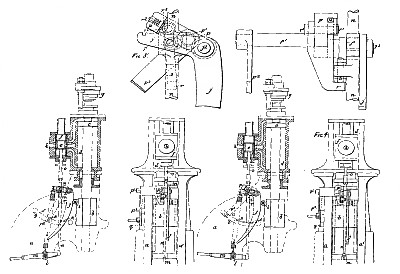
My invention relates to steam-hammers and other hammers worked by the pressure of elastic fluids, and has for its object the provision of means simpler, more convenient and more efficient than those hitherto provided for such purpose, to enable such hammers to be used as stamps whenever it may be desirable to so use them, at which times the tups of such hammers are required to remain away from the anvils employed in conjunction with them until required to strike a blow or make a stroke and then to strike such blow or make such stroke and afterwards return and remain away from the said anvils until the next blow or stroke is required to be struck or made.
Claim:
In a steam-hammer or other hammer worked by the pressure of elastic fluid, the combination with the valve-rod or other suitable part connected to the valve or valves employed to control the admission and release of steam or other motive fluid to and from the cylinder of the hammer, of a spring or springs or weight or weights or piston or pistons acted upon by the pressure of steam or other fluid or other means tending tb move the said valve or valves so as to cause the tup of the hammer to be moved away from the anvil employed in conjunction with it, an arm arranged to be moved as may be requisite from time to time by means of a lever held in the various positions requisite by any suitable means such as a quadrant and detent, a stop or catch upon the said arm, and a stop or catch upon the valve-rod or other suitable part connected to the said valve or valves to act in conjunction with the stop or catch upon the said arm so as to limit at such times as the stop or catch upon the said arm is brought into the path of the stop or catch upon the valve-rod or other suitable part connected to the said valve or valves, the movement of the valve or valves aforesaid in the direction for causing the tup of the hammer to be moved away from the anvil employed in conjunction with it, all arranged, employed and operating substantially in the manner hereinbefore described and for the purpose of enabling the said hammer to he readily caused to operate as a stamp. |
|




)
)