US Patent: 833,758
|
| Wire Straightening and Cutting Machine
|
|
Patentee:
|
|
| Franklin B. Shuster (exact or similar names) - New Haven, New Haven County, CT |
|
|
Patent Dates:
|
| Applied: |
Dec. 20, 1902 |
| Granted: |
Oct. 23, 1906 |
|
Patent Pictures:
[
1 | 2 | 3 | 4 | 5 | 6
]
|
|
|
USPTO (New site tip)
Google Patents
Report data errors or omissions to steward
Joel Havens
"Vintage Machinery" entry for F. B. Shuster Co.
|
|
Description: |
| Abstract:
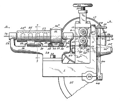
Heretofore in wire straightening and cutting-off machines double standards carrying the boxes (four in number) of the feed-roll shafts were used, and as often as the size of the wire run through the machine was changed it was of course necessary to change the vertical position of the feed-rolls. To insure the engagement of the feed-roll-shaft gears for the different vertical positions it was necessary to make the teeth of these gears long enough to meet these varying positions. This construction had a tendency to weaken the gears and cause frequent breakage. Then, again, the four independent boxes were difficult to adjust and keep in alinement with the wire-feeding line. With my improved construction only one standard is required in which, as before mentioned, the forward ends only of the boxes are mounted and adjusted, while their opposite ends are permanently located in one position, thus leaving their forward ends free to be adjusted to the feeding-line of the wire, while the vertical position of the ordinary tooth-gears 15 and 16 are not perceptibly changed. This not only makes a handier construction, but it is decidedly cheaper.
Claim:
The combination, in a wire straightening and cutting-off machine, comprising shafts carrying gears and wire-feeding rolls, boxes in which said shafts are journaled, said boxes located between said gears and feeding-rolls, both of said boxes pivotally supported at or near one end to a stationary part of the machine, the opposite end of said boxes adjustably supported. |
|




)
)
)
)
)
)