US Patent: 70,483
|
| Lathe Way Smoother
|
|
Patentee:
|
|
| Alfred Thomas (exact or similar names) - Worcester, MA |
| Manufacturer: |
| Not known to have been produced |
|
|
Patent Dates:
|
| Granted: |
Nov. 05, 1867 |
USPTO (New site tip)
Google Patents
Report data errors or omissions to steward
Joel Havens
"Vintage Machinery" entry for Thomas Iron Works
|
|
Description: |
| Thomas H. Dodge - patent attorney
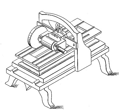
To enable those skilled in the art to which my invention belongs to make and use the same, I will proceed to describe it more in detail. In the drawings, A represents the stationary bed of an ordinary planing machine, and B the movable bed, which works on the ways a a, and may be moved back and forth in the ordinary manner. C is the frame, which supports the planing-tool, and which also serves to support the lathe-way smoothing apparatus. D is a bed of a lathe arranged upon the movable bed or table B, and fastened thereto by cross-pieces 6 and bolts a. The ways d d of the bed D have heretofore been finished by a hand-file-, an operation both tedious and expensive, but which operation can be performed by my improved mechanism in a very uniform and expeditious manner. To the slide-piece E is fastened the frame F, in the arms G G of which is supported in suitable bearings a shaft, H, having a pulley, I, upon its centre, while, its ends extend on either side sufficiently far to support the smoothing and reducing-wheel J. The slide-piece E is dove-tailed to the piece K, which, in turn, is dove-tailed to the cross-piece or bar L. The piece K can be moved upon the cross-bar L to adjust the smoothing and reducing wheel J to any desired position, and a screw-shaft may be employed for such purpose, the same as in the common planing machine. Frame F is fastened to the piece E by means of tlie screws or bolts ef, the latter passing through the curved groove g in the frame F. By loosening the screws or bolts ef, frame F can be tipped laterally to adjust the wheel J to work upon any desired angle.
|
|