US Patent: 1,832,011
|
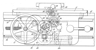
| Clutch Mechanism for Lathe Carriages
|
|
Patentees:
|
| Alfred C. Getz (exact or similar names) - Sidney, Shelby County, OH |
| Frederick D. Dickas (exact or similar names) - Sidney, Shelby County, OH |
|
|
Patent Dates:
|
| Applied: |
Jun. 03, 1929 |
| Granted: |
Nov. 17, 1931 |
|
Patent Pictures:
[
1 | 2
]
|
|
|
USPTO (New site tip)
Google Patents
Report data errors or omissions to steward
Joel Havens
"Vintage Machinery" entry for Sidney Tool Co.
|
|
Description: |
| Siggers & Adams - patent attorney
Abstract:
This invention relates to clutch mechanisms for the power feed of lathe carriages and cross slides and aims, among other objects, to provide improved positive clutches and clutch control means, particularly adapted to enable the clutches to be operated very quickly and conveniently. Referring particularly to the drawings, the improved clutches and control means are there shown as embodied in a lathe apron, secured to a carriage which is slidable longitudinally in the ways on a lathe bed and on the carriage a cross slide is slidably mounted. The carriage is adapted to be propelled along the lathe bed by a spur gear carried by the apron and engaging a stationary rack on the lathe, the gear being driven either by power, through a train of gearing from the feed rod, or manually by means of a hand wheel. The cross slide is adapted to be moved transversely on-the carriage by means of a cross-feed screw shaft so the shaft being rotated either by power, through another train of gearing from the feed rod, or by a handle. The direction of travel of the carriage or the cross slide is controlled by a handle, which manipulates the reversing bevel gears.
Claim:
In a lathe apron having trains of gearing for the longitudinal and cross-feeds; positive clutch means in each of said trains; each clutch means including a pair of clutch elements ;means normally holding said elements disengaged; and snap-action clutch operating means for each of said clutches, each of said clutch operating means including a shaft operatively connected to one of said clutch elements and projecting beyond the front of the apron; a rotatable plate surrounding the shaft and abutting the front of the apron; a bifurcated lever having its arms pivotally connected to the projected end of the shaft; said arms having flat side and end bearing faces arranged at an obtuse angle to each other and adapted to engage the plate, the angle between the faces being such and the pivot being so located with respect to the 1faces that when the end faces are engaged with the plate the clutch elements are entirely engaged and when the side faces are engaged with the plate the elements are entirely disengaged.
|
|

)
)