US Patent: 266,456
|
| Traction Engine
|
|
Patentee:
|
|
| Abraham O. Frick (exact or similar names) - Waynesborough, Franklin County, PA |
| Manufacturer: |
|
Frick Co. - Waynesboro, Franklin County, PA |
|
|
Patent Dates:
|
| Applied: |
Sep. 05, 1882 |
| Granted: |
Oct. 24, 1882 |
USPTO (New site tip)
Google Patents
Report data errors or omissions to steward
Joel Havens
"Vintage Machinery" entry for Frick Co.
|
|
Description: |
| Abstract:
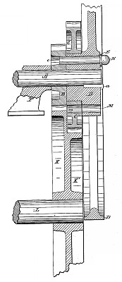
My invention relates to traction engines which use a fly-wheel for evening and steadying the motion by giving off the power, to aid in sudden emergencies or in intermittent strains, which has been accumulated in the intervals between severe labor, said fly-wheel serving also as a band-wheel when doing local work; and the objects of my improvements are, first, to provide means whereby the fly-wheel may be readily connected with a spur-wheel for the purpose of operating the traction-wheels, or disconnected therefrom when using the handwheel in local work; second, to provide means whereby two rates of speed may be given to the traction-wheels in order that more force may be applied to the traction-wheels for ascending hills, the engine advancing along the road at a rate proportionally slower as the force applied is increased, the engine revolving all the time at the same speed and producing the same amount of power. I attain these objects by mechanism hereinafter fully described and claimed, reference being had to the accompanying drawing, which is a sectional elevation, longitudinal with respect to the engine-shaft.
Claim:
The combination, with the spur-wheel K, shaft L, pillow-block F, main shaft A, and flywheel D, secured thereon and provided with a turned hub for a bearing for the gear-wheel O, of the pin-hole E, extending through the hub of wheel D, and said turned bearing thereon, the pin-hole c in wheel B, within the circle of its teeth, and the pin H, fitted easily in holes E e. |
|