US Patent: 52,959
|
| Oiler
|
|
Patentee:
|
|
| John Broughton (exact or similar names) - New York, NY |
|
|
Patent Dates:
|
| Granted: |
Mar. 06, 1866 |
| Reissue Information: |
| Reissued as RE2,686 (Jul. 16, 1867) |
|
Patent Pictures:
[
1 | 2
]
|
|
|
USPTO (New site tip)
Google Patents
Report data errors or omissions to steward
Joel Havens
|
|
Description: |
| Abstract:
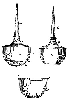
First, to so construct a spring-bottom oiler that no soldered joint is required to connect such spring-bottom with the sides of the reservoir, thus rendering it less liable to become leaky by the action of the bottom or by being placed in a hot position, than spring-bottom oilers of the ordinary construction. This is accomplished by forming the spring-bottom and the sides of the reservoir of one, piece and ,joining the same to a rigid cover, the joint thus being in an elevated position where it cannot be incited when the oiler is placed upon a hot stove. Second, to form a rigid or inflexible external surface to the entire oiler, except at the point where the thumb is placed when operating it, so that the flexible bottom is protected from injury by bruising or from accidental punctures. This is accomplished by inclosing the reservoir below the cover-joint in a strong shell or casing (said shell conforming to tile shape of the reservoir) and providing the shell with an opening in the bottom through which the spring-bottom may be reached and operated. Third, to provide a method of operating the spring-bottom of an oiler so that it cannot be forced inward beyond the limit of its elasticity, thus insuring the retention of the spring or elasticity in the bottom as long as the oiler lasts. This is accomplished by forming an internal flange in the opening through the bottom of shell T and providing an operating thumb-piece, G, with two heads, an internal and an external one, the two being connected by a center pin or rivet. The internal head rests upon the flange of the shell G, which prevents it from dropping out. The external head spans the flange on the shell in a similar manner, an annular space being between the two heads. This annular space corresponds in depth to the motion to be given to the spring- bottom, and when the thumb is pressed on the external head, G, the spring-bottom is compressed and moves inward until ,ail head rests upon the flange of the shell, thus forming a stop within the limit of the elasticity of the bottom, and beyond which it cannot be forced. Fourth, to arrange and construct a spring-bottom oiler in such manner that while the said bottom is compressed and operated by the thumb in the ordinary manner, its lower external portion shall form a rolling surface with the center of gravity near the bottom, so that it will not upset. This is accomplished by making the lower half of the reservoir in the form of a zone, the curve of the enveloping-shell conforming to it and the continuation of such shell downward, approximating in shape to a semi sphere, leaving a recess or space between itself and the spring-bottom in which to place the operating thumb-piece, which, necessarily being of a diameter large enough to place the thumb upon, forms a counterpoise to the upper portion of the reservoir and the tube, without any special provision for that purpose.
Claim:
In oilers provided with elastic or spring bottoms, forming the sides of the reservoir and said spring-bottom in one piece. |
|

)
)