US Patent: 821,236
|
| Valve Gear for Engines
|
|
Patentee:
|
|
| Theodore H. Haberkorn (exact or similar names) - Fort Wayne, Allen County, IN |
| Manufacturer: |
| Not known to have been produced |
|
|
Patent Dates:
|
| Applied: |
Dec. 05, 1905 |
| Granted: |
May 22, 1906 |
|
Patent Pictures:
[
1 | 2 | 3 | 4 | 5 | 6
]
|
|
|
USPTO (New site tip)
Google Patents
Report data errors or omissions to steward
Joel Havens
|
|
Description: |
| Abstract:
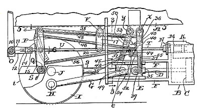
This invention relates to improvements in valve-gears for engines operated by fluid under pressure, and pertains more especially to a reversible double steam-engine for a locomotive. The primary object of this invention is to overcome the defects of valve-gears operated by eccentrics. The attachment of such eccentrics to the driving shaft or axle frequently causes trouble by heating and constantly disturbs the steam distribution, especially in locomotives where such axle never remains in alinement with the valve mechanism, which is attached to frames vibrating on springs. The depression of the springs and the lost motion of eccentrics, journal-bearings, and axle-boxes which are held loose between frames to permit the sliding motion caused by the springs make a valve-gear comprising eccentrics not only defective and wasteful in fuel consumption, but also expensive by frequent adjustments and repairs. The valve-gear or valve-motion is the life of an engine, and a defective valve-motion produces a defective engine.
Claim:
In a valve-gear for a double engine operated by fluid under pressure, the combination, with the two valves and the two piston- operated cross-heads, of two parallel shafts provided respectively with a power-receiving arm and two power-transmitting arms, with the latter unequal in length and with the power-receiving arm of one of the shafts operatively connected with one of the crossheads and with the power-receiving arm of the other shaft operatively connected with the other crosshead; a link connection between the shorter power-transmitting arm of each shaft and the longer power-transmitting arm of the other shaft, which link connection comprises two links of unequal length, with the longer link pivoted at one end to one end of the shorter link and at its opposite end to the shorter shaft-arm and with the shorter link pivoted at its opposite end to the longer shaft-arm; means for transmitting motion from the longer link of one of the link connections to one of the valves, and means for transmitting motion from the longer link of the other link connection to the other valve, and the axes of the pivotal connections of the shorter link of each link connection being spaced correspondingly with the distance between the axes of the shafts. |
|

)
)
)
)
)
)